Vacuum eutectic welding method

A technology of vacuum eutectic welding and eutectic furnace, which is applied in the direction of electrical components, semiconductor/solid-state device manufacturing, circuits, etc., can solve the problems of low heating efficiency, accelerated chip, failure, etc., achieve low cost, avoid chip over-soldering, The effect of high yield

Inactive Publication Date: 2012-07-04
WUXI HUACE ELECTRONICS SYST
View PDF6 Cites 45 Cited by
  • Summary
  • Abstract
  • Description
  • Claims
  • Application Information

AI Technical Summary

Problems solved by technology

The disadvantages of this are: 1. Because the solder sheet used for eutectic welding has been partially oxidized during production, storage and transportation, oxidation residues will be generated during vacuum eutectic welding; 2. T

Method used


Image

  • Vacuum eutectic welding method
  • Vacuum eutectic welding method

Examples


Embodiment Construction

[0027] The method adopted in this embodiment is:

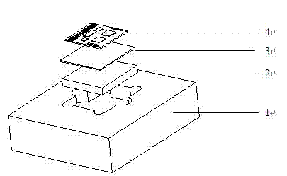
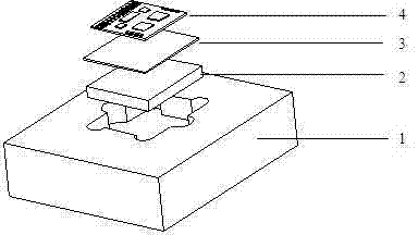
[0028] 1. Design and process a kind of tooling. The material of the tooling is high-purity graphite plate. Several square grooves are milled on the graphite plate, and two semicircular grooves are milled on a group of opposite sides of the square grooves, which are used for taking and placing heat sinks, preheating Forming solder sheets and chips;

[0029] 2. Clean the graphite tooling and install it into the process chamber of the vacuum eutectic furnace;

[0030] 3. Clean the heat sink and preformed solder sheet;

[0031] 4. Put the heat sink, preformed solder sheet and chip into the square groove of the graphite tooling in turn;

[0032] 5. Close the cover plate of the process chamber of the vacuum eutectic furnace;

[0033] 6. The process chamber is vacuumed, filled with nitrogen, and then vacuumed again, and the oxygen and water vapor in the chamber are removed by repeated vacuuming and nitrogen filling, and the atmosp...


PUM


Abstract

The invention belongs to a micro-electronic encapsulation technology and specifically relates to a vacuum eutectic welding method. The method comprises the following steps: reducing gas formic acid vapor or hydrogen is introduced during a vacuum eutectic welding process, so as to reduce an oxidized welding material on a surface layer of a preformed welding material sheet and reduce the oxidized dreg of a welded surface; during a heating process, nitrogen is introduced and the heating rate is increased, so as to shorten the eutectic time and avoid the efficacy loss caused by chip over-welding or high-temperature accelerated ageing; and vacuumizing is carried out during an eutectic process, so as to reduce and even avoid voidage of the welded surface, increase the penetration rate of the chip and reduce the contact resistance and thermal resistance. According to the invention, the problem of the oxidized dreg on the welded surface caused by the oxidation of the surface layer of the welding material sheet in the prior art is overcome; the demand on storage conditions of the welding material sheet is reduced; the eutectic time is shortened; the efficacy loss caused by chip over-welding or high-temperature accelerated ageing is avoided; the void ratio is reduced; and the vacuum eutectic welding method has the characteristics of high reliability, high yield and low cost.

Description

technical field [0001] The invention relates to the field of electronic device welding, in particular to a vacuum eutectic welding method. Background technique [0002] Microelectronic packaging consists of several process steps, of which the bonding between the chip and the heat sink is a critical step. The traditional process method is to use conductive adhesive for bonding. After bonding, the resistivity is large and the thermal conductivity is small, resulting in large microwave loss, large thermal resistance of the die and heat sink, high junction temperature, and limited power output, resulting in performance indicators of circuit components. and reduced reliability, unable to meet the assembly requirements of military hybrid circuit assemblies. [0003] At present, eutectic welding is the most widely used in microelectronic packaging, especially military electronic devices and components are further developed in the direction of multi-functional integration and minia...

Claims


Application Information

Patent Timeline
IPC IPC(8): B23K1/008H01L21/60
Inventor 刘立安徐学林
Owner WUXI HUACE ELECTRONICS SYST
Why Eureka
Try Eureka