High-efficiency diamond bit and production process thereof

A diamond drill bit and production process technology, applied in the field of mechanical processing, can solve the problems of poor wear resistance, poor sharpness, affecting the production efficiency of processed stone, etc., and achieve the effects of strong wear resistance, not easy to fall off, and stable welding method

Active Publication Date: 2012-07-04
福建省泉州万龙石业有限公司
View PDF8 Cites 26 Cited by
  • Summary
  • Abstract
  • Description
  • Claims
  • Application Information

AI Technical Summary

Problems solved by technology

[0004] The invention provides a high-efficiency diamond drill bit and its production process, the main purpose of which is to overcome the defects of poor sharpness, poor wear resistance and affecting the production efficiency of stone processing existing in the existing diamond drill bit

Method used


Image

  • High-efficiency diamond bit and production process thereof
  • High-efficiency diamond bit and production process thereof
  • High-efficiency diamond bit and production process thereof

Examples


Embodiment 1

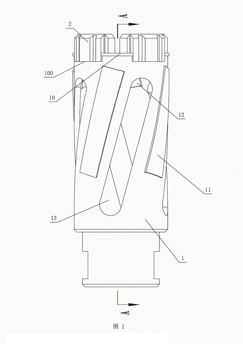
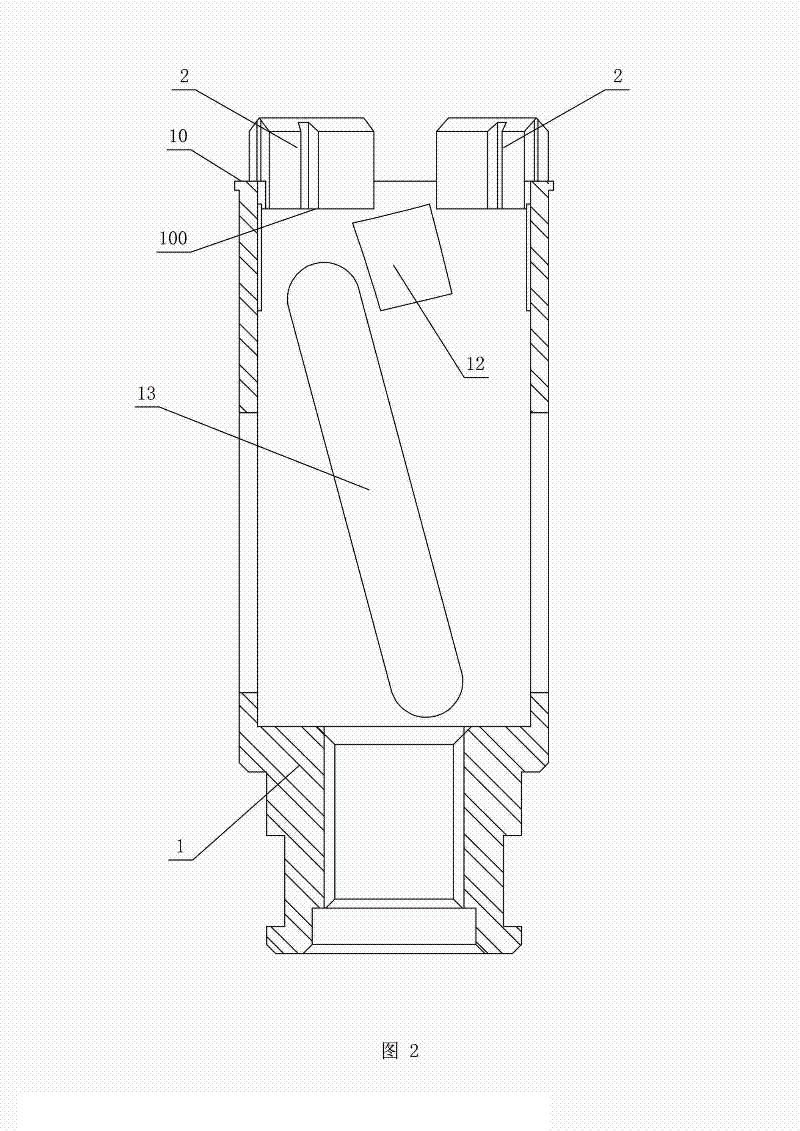
[0025] refer to figure 1 and figure 2 . A high-efficiency diamond drill bit, including a substrate and a cutter head 2, the substrate is a steel substrate 1, and its top end surface 10 is provided with a notch 100 for assembling the cutter head 2, and the connecting part of the cutter head 2 is welded in the notch 100 , the depth of the notch 100 is 3 mm.

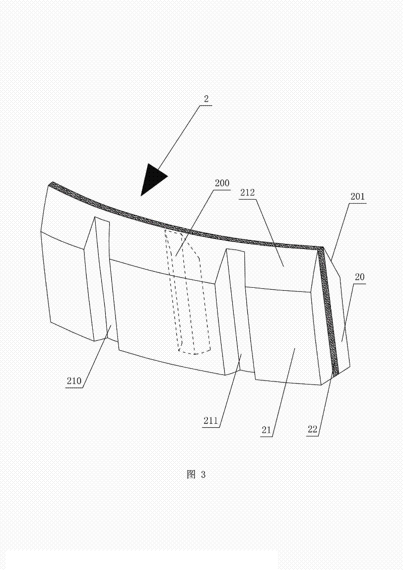
[0026] refer to figure 1 and image 3 . The cutter head 2 is composed of an inner sharp carcass 20, an outer sharp carcass 21, and a wear-resistant hard carcass 22 sandwiched between the inner and outer sharp carcass. The thickness of the wear-resistant hard carcass 22 is approximately The inner and outer sharp carcass 20, 21 and wear-resistant hard carcass 22 are sintered and formed by mixing diamond particles and pre-alloyed powder. The pre-alloyed powders of the inner and outer sharp carcass 20, 21 all include the following components by weight percentage: 41% cobalt, 22% iron, 6% nickel, 24% copper, and 7% tin; t...

Embodiment 2

[0037]The implementation of this embodiment is basically the same as that of Embodiment 1, the difference is that the sharp carcass is made by atomization treatment according to the weight percentage configuration of 39% cobalt, 20% iron, 8% nickel, 25% copper, and 8% tin Pre-alloyed powder; according to the weight percentage of 36% cobalt, 17% iron, 10% nickel, 9% tungsten, 20% copper, and 8% tin, the pre-alloyed powder made of wear-resistant hard matrix is ​​prepared through atomization treatment; The proportion by weight is diamond particles: pre-alloyed powder = 3:97.

Embodiment 3

[0039] The implementation of this example and Example 1 is basically the same, the difference is that the sharp carcass is made by atomization treatment according to the weight percentage configuration of 40% cobalt, 18% iron, 10% nickel, 26% copper, and 6% tin Pre-alloyed powder; according to the weight percentage of 40% cobalt, 14% iron, 8% nickel, 6% tungsten, 23% copper, and 9% tin, the pre-alloyed powder made of wear-resistant hard matrix is ​​prepared through atomization treatment; The proportion by weight is diamond particles: pre-alloyed powder = 5:95.


PUM

PropertyMeasurementUnit
depthaaaaaaaaaa
thicknessaaaaaaaaaa

Abstract

A high-efficiency diamond bit comprises a base and a tool bit fixedly disposed on the base. The tool bit consists of an inner sharp blank, an outer sharp blank and a wear-resistant hard blank sandwiched between the inner sharp blank and the outer sharp blank, and diamond particles and pre-alloyed powder are sintered after being mixed to form each of the inner sharp blank, the outer sharp blank and the wear-resistant hard blank. The tool bit is a sandwich type structure, namely, the wear-resistant hard blank is sandwiched between the inner sharp blank and the outer sharp blank, and excellent sharpness of the top of the tool bit is improved. In addition, when the tool bit grinds, the hardness of the inner sharp blank and the hardness of the outer sharp blank are lower than the hardness of the wear-resistant hard blank, accordingly, a triangular pointed edge can be constantly formed on the top of the tool bit, an excellent self-sharpening performance and excellent sharpness of the cutting head are constantly kept, and cutting force is high.

Description

technical field [0001] The invention belongs to the field of mechanical processing, and specifically refers to a high-efficiency diamond drill bit and a production process. Background technique [0002] The drill bit used as the cutting edge is called a diamond drill bit, which includes a cutter head and a steel substrate, and the cutter head is directly fixed on the top end surface of the steel substrate by welding. Taking cutting stone as an example, the steel base of the diamond drill bit is fixed on the machine, and the rotating mechanism on the machine drives the diamond drill bit to rotate and cut the stone. [0003] At present, the cutter head of the diamond drill bit is generally formed by mixing diamond particles and metal powder and then sintering. Poor, and the ratio of components in the existing metal powder is not ideal, resulting in poor wear resistance of the cutter head. In the stone grinding process, a diamond drill can only drill 100 holes in general, the...

Claims


Application Information

Patent Timeline
Patent Type & Authority Applications(China)
IPC IPC(8): B28D1/14B22F3/14
Inventor 涂连和黄莹祥许晓旺申思郭镇义
Owner 福建省泉州万龙石业有限公司
Why Eureka
Try Eureka