Method and system for improving sensing performance of long-distance Brillouin optical time domain analysis system

An optical time-domain analysis and long-distance technology, which is applied in the field of optical fiber, can solve problems such as high requirements, more serious fluctuations, and low signal-to-noise ratio, and achieve the goals of improving spatial resolution, improving sensing performance, and improving pumping efficiency. Effect

Inactive Publication Date: 2012-07-04
WUXI CHENGDIAN OPTICAL FIBER SENSING TECH
View PDF3 Cites 18 Cited by
  • Summary
  • Abstract
  • Description
  • Claims
  • Application Information

AI Technical Summary

Problems solved by technology

However, in the long-distance (>50km) Brillouin optical sensing system, due to the exponential attenuation of the Raman pump power and Raman gain coefficient along the optical fiber, this method cannot completely eliminate the uneven power distribution, and the sensing The longer the distance, the more severe the fluctuation
The result is a large, low signal-to-noise ratio measurement "blind spot" in the sensing signal distribution
On the other hand, the efficiency of first-order Raman pumping is low, and in long-distance sensing systems, the requirement for Raman pump power is high, which seriously increases the system cost

Method used


Image

  • Method and system for improving sensing performance of long-distance Brillouin optical time domain analysis system
  • Method and system for improving sensing performance of long-distance Brillouin optical time domain analysis system
  • Method and system for improving sensing performance of long-distance Brillouin optical time domain analysis system

Examples


Embodiment Construction

[0022]In order to make the purpose, technical solution and advantages of the present invention clearer, the present invention will be further described in detail below in conjunction with the accompanying drawings and specific implementation.

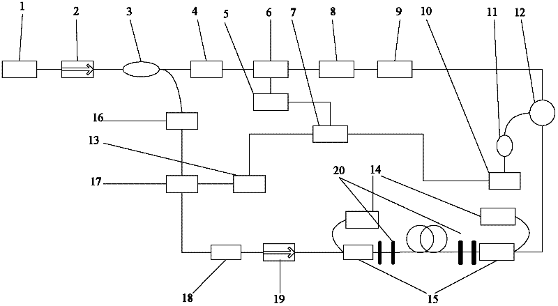
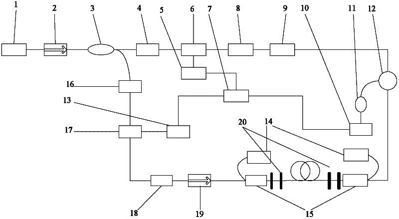
[0023] figure 1 It is the structural diagram of the long-distance Brillouin optical time-domain analysis sensing system based on Raman hybrid amplification provided by the present invention, such as figure 1 As shown, the long-distance Brillouin optical time domain analysis sensing system based on Raman hybrid amplification of the present invention includes the Brillouin optical time domain analysis sensing system of the first-order bidirectional Raman amplification and the Raman hybrid amplification sensing system. System; the Brillouin optical time-domain analysis and sensing system of the first-order bidirectional Raman amplification specifically includes: a laser 1, a first isolator 2, a coupler 3, a first polarization controller 4,...


PUM

PropertyMeasurementUnit
reflectanceaaaaaaaaaa

Abstract

The invention discloses a method and system for improving sensing performance of a long-distance Brillouin optical time domain analysis system. On the basis of the existing long-distance Brillouin optical time domain analysis system which uses a first-order Raman amplification technique, a pair of optical fiber gratings with peak reflectivity being larger than 80 percent and consistent central reflection wavelength are fused on the two sides of sensing optical fibers to form a long-distance laser resonant cavity. Laser generated by the laser resonant cavity is used as a second-order Raman pump and a first-order Raman pump to simultaneously take an effect of amplifying sensing signals. Compared with a Brillouin sensing system which is based on the first-order Raman amplification, under the conditions of the same pump power, the method and the system provided by the invention have the advantages that higher grains can be obtained and the pump efficiency is improved; the sensing signals are distributed more smoothly along the optical fibers; when the system is used for long-distance temperature/stress sensing, the spatial resolution, the measurement accuracy and the sensitivity of the monitoring system can be greatly improved; and the sensing performance is obviously improved at a low cost without increasing an additional second-order pump light source.

Description

technical field [0001] The invention relates to the field of optical fiber technology, in particular to a method and system for improving the sensing performance of a long-distance Brillouin optical time-domain analysis system based on Raman hybrid amplification technology. Background technique [0002] The distributed optical fiber sensing technology based on Brillouin scattering has higher measurement accuracy, measurement range and spatial resolution in temperature and strain measurement than other sensing technologies. Therefore, this technology is widely used in building structure monitoring, oil pipeline safety It has broad application prospects in areas such as detection, health detection of power facilities, and fire warning. According to whether the stimulated Brillouin effect is used, it is generally divided into two types: Brillouin optical time domain reflectometer and Brillouin optical time domain analyzer. The former uses the spontaneous Brillouin scattering ph...

Claims


Application Information

Patent Timeline
Patent Type & Authority Applications(China)
IPC IPC(8): G01D5/353G01B11/16G01K11/32G01K11/3206G01K11/322
Inventor 饶云江贾新鸿张田虎
Owner WUXI CHENGDIAN OPTICAL FIBER SENSING TECH
Why Eureka
Try Eureka