
High-accuracy wireless clock synchronization system for power system

A wireless clock and power system technology, applied in synchronization devices, wireless communication, transmission systems, etc., can solve problems such as inability to achieve high-precision clock synchronization, affect clock synchronization accuracy, and exist uncertain delays, so as to save construction costs and the difficulty of engineering construction, the effect of reducing the dependence on GPS, improving reliability and safety

Inactive Publication Date: 2012-07-04
UNIV OF ELECTRONIC SCI & TECH OF CHINA +1
View PDF3 Cites 38 Cited by
  • Summary
  • Abstract
  • Description
  • Claims
  • Application Information

AI Technical Summary

Problems solved by technology

[0011] The clock synchronization method based on software time stamps detects and identifies time stamps on the application layer through software methods. Although the synchronization accuracy of this method has been further improved compared with the traditional NTP time synchronization method, due to the TCP / IP protocol definition The data transmission of the network interface layer (data link layer and physical layer), network layer, transport layer and application layer has uncertain delay in each layer, which greatly reduces the synchronization accuracy.
[0012] The clock synchronization method based on hardware time stamp, such as the authorized announcement on June 1, 2011, the announcement number is CN101242231B, and the Chinese invention patent named "a clock synchronization device for power system synchrophasor measurement" adopts the The TCP / IP protocol stack hardware implementation module is added to the front end of the data link layer to transfer the time stamp identification from the application layer to the data link layer. Although this method avoids the network layer and transport layer with large delay and jitter, The synchronization performance is higher than that of the software time stamp method, but there are still uncertain delays in the driver program of the data link layer and its interrupt response, and the processing time of the interrupt varies with the performance and structural configuration of the CPU or control logic module of the clock synchronization device. The differences vary, which affects the accuracy of its clock synchronization, so that it cannot achieve wide-area high-precision clock synchronization

Method used


Image

  • High-accuracy wireless clock synchronization system for power system
  • High-accuracy wireless clock synchronization system for power system
  • High-accuracy wireless clock synchronization system for power system

Examples


Embodiment

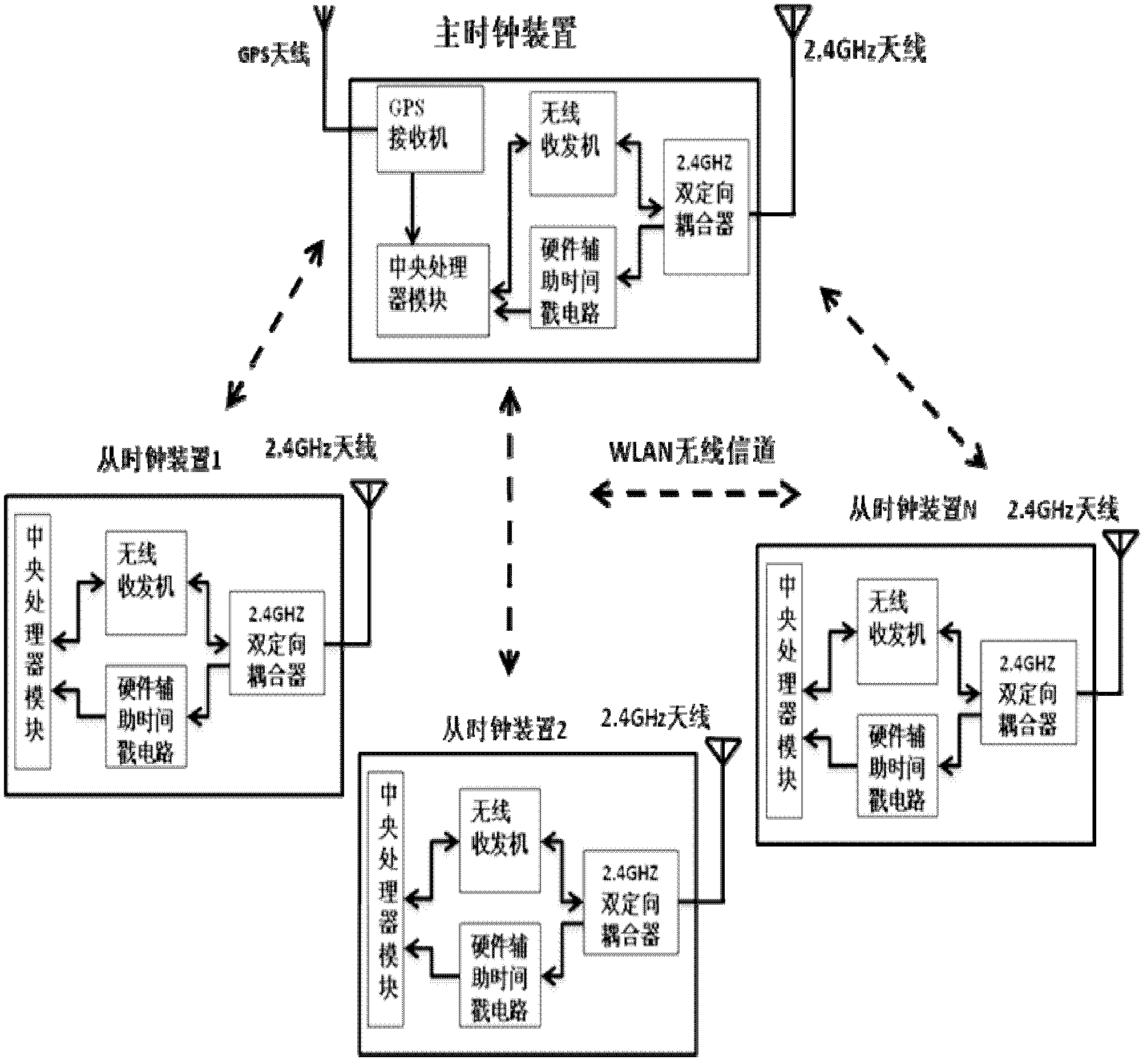
[0036] figure 1 It is a principle diagram of a specific implementation mode of the high-precision wireless clock synchronization system oriented to the power system of the present invention

[0037] In this example, if figure 1 As shown, the high-precision wireless clock synchronization system oriented to the power system of the present invention is composed of a master clock device, a plurality of slave clock devices and a WLAN wireless channel. The master clock device includes GPS antenna, GPS receiver, 2.4GHz antenna, wireless transceiver, hardware-assisted time stamp circuit, 2.4GHz dual directional coupler and CPU module. The slave clock device includes 2.4GHz antenna, wireless transceiver, hardware-assisted time stamp circuit, 2.4GHz dual directional coupler and CPU module. The master clock device is connected with the slave clock device through the WLAN wireless channel to form a synchronous timing network.

[0038] In this embodiment, the main clock device can not o...


PUM


Abstract

The invention discloses a high-accuracy wireless clock synchronization system for a power system. A hardware assisting timestamp circuit is added in a physical layer, the identification of the timestamp is transferred from a traditional application layer or a MAC (Medium Access Control) sub-layer of a data link layer to a PHY (physical layer); the timestamp information is transferred to a central processor. Compared with the hardware timestamp method of the prior art, because the driving program of the MAC (Medium Access Control) sub-layer and the uncertain time delay for the interruption response of the driving program are avoided further, the time synchronization accuracy is higher, at the same time, the reliability and the safety are improved further, the requirement that each distribution-type system has high clock synchronization accuracy is met, and the power system oriented high-accuracy wireless clock synchronization system is not suitable for application occasions with laid cables.

Description

technical field [0001] The invention belongs to the technical field of clock synchronization, and more specifically relates to a high-precision wireless clock synchronization system oriented to electric power systems. Background technique [0002] In recent years, with the continuous expansion of the scope of wireless distributed systems and the gradual improvement of decentralized control capabilities, many important fields, such as power systems, oil exploration, industrial automation, aviation and aerospace fields, etc., need to control various intelligent electronic devices. Schedule and control in real time. Most of these intelligent electronic devices require a unified time reference to operate normally, and time synchronization of each device is a basic condition for a distributed system. At the same time, due to the rapid development of computer communication technology and microelectronics technology, more and more control systems require high-precision synchroniza...

Claims


Application Information

Patent Timeline
IPC IPC(8): H04L29/08H04W56/00
Inventor 黄琦井实甄威陈班贤孟劲松王彪易建波张华谢强强吴杰
Owner UNIV OF ELECTRONIC SCI & TECH OF CHINA
Learn More