
Acousto-optic deflector with phase-controlled transducer array

An acousto-optic deflector and transducer array technology, applied in the field of laser scanning, can solve the problems of high system complexity, poor effect, large tracking error, etc., and achieve the effects of reducing device cost, increasing length, and enhancing practicability

Inactive Publication Date: 2012-07-11
HUAZHONG UNIV OF SCI & TECH
View PDF6 Cites 20 Cited by
  • Summary
  • Abstract
  • Description
  • Claims
  • Application Information

AI Technical Summary

Problems solved by technology

However, in "Generalized phased array Bragg interaction in anisotropic crystals", Eddie H. Young at el, Optical Technology for Microwave Applications V, 1991 pointed out that when using the first-level tracking method to track the Bragg angle near the extreme point, the tracking error is large , the effect is not as good as the case of fast mode incidence
[0010] Another implementation of the phase-controlled transducer array uses multiple independent RF drive sources to drive the transducer array, which can achieve complete tracking with zero tracking error. This implementation method is rarely used due to high system complexity. is adopted, but the tracking effect is significantly better than the first-level tracking method

Method used


Image

  • Acousto-optic deflector with phase-controlled transducer array
  • Acousto-optic deflector with phase-controlled transducer array
  • Acousto-optic deflector with phase-controlled transducer array

Examples


Embodiment Construction

[0036] The present invention will be further described below in conjunction with the accompanying drawings.

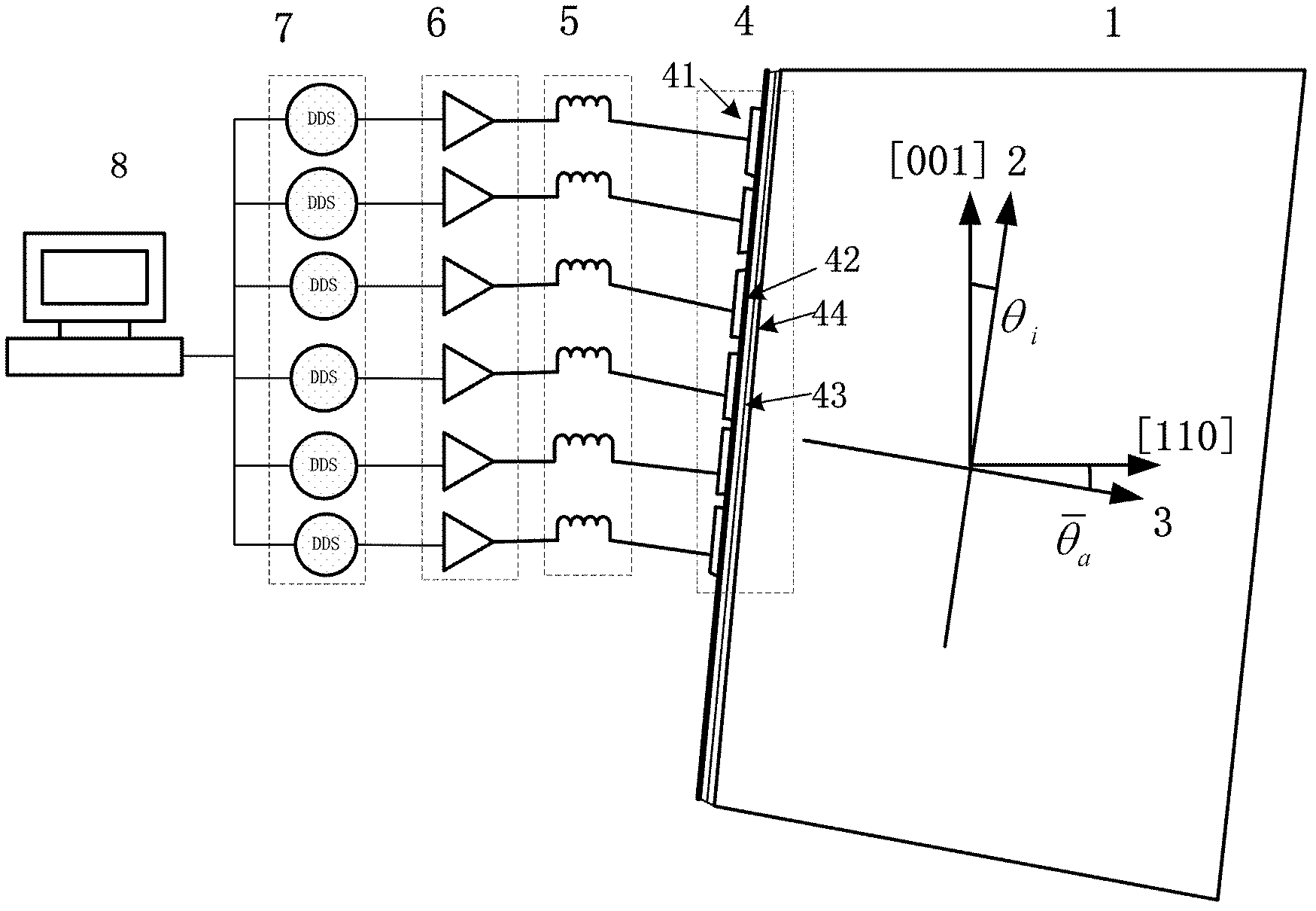
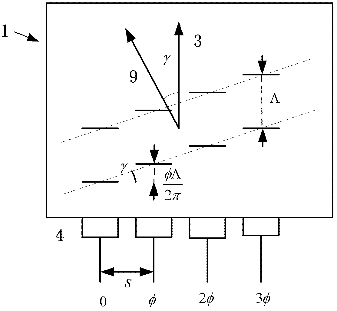
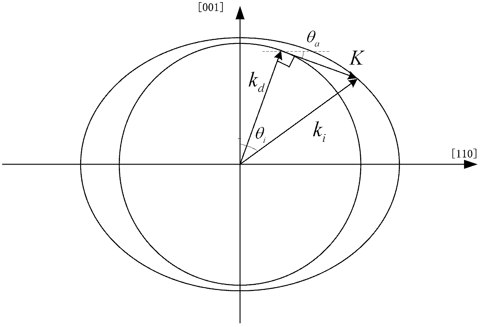
[0037] figure 1 It is a schematic diagram of the structure of the phase-controlled transducer array acousto-optic deflector. In the figure, 1 is the acousto-optic crystal, 2 is the direction of incident light, and 3 is the normal line of the transducer plane. In this example, tellurium dioxide is selected as the acousto-optic material because of its small sound velocity and large acousto-optic figure of merit, which makes it easy to realize a large dynamic scanning angle. Ultrasound is a slow shear wave, and the direction of propagation is basically along the [110] crystal direction of tellurium dioxide, forming an angle with [110] Called the transducer off-axis angle, the incident light forms a small angle θ with the [001] directioni . 4 is a piezoelectric transducer array, the piezoelectric transducer array is welded on the surface of the acousto-optic crystal, 5 ...


PUM


Abstract

The invention particularly relates to an acousto-optic deflector with a phase-controlled transducer array. A plurality of transducer electrodes are arranged on a piezoelectric layer on the surface of acousto-optic crystals, and are driven by an independent radio frequency (RF) signal source; the phase difference between RF signals is adjustable; and the acousto-optic deflector works in an abnormal Bragg diffraction mode and can increase the bandwidth by adopting slow-mode incident light and tangent conditions. The range of the tracking angle desired for ultrasonic tracking can be reduced by adopting the tangent conditions of abnormal Bragg diffraction, thereby further increasing length of a single transducer electrode, improving acousto-optic interaction length, or reducing the number of desired transducer electrodes, and reducing system complexity. The acousto-optic deflector can be widely used in the application fields of microscopic imaging, laser display and record system, laser processing, laser measurement and control, and so on.

Description

technical field [0001] The invention belongs to the technical field of laser scanning, and in particular relates to an acousto-optic deflector with a phase-controlled transducer array. Background technique [0002] The acousto-optic deflector is a diffraction device that deflects the light beam by using the acousto-optic coupling effect. Its principle is to generate ultrasonic waves by the ultrasonic piezoelectric transducer bonded on the surface of the acousto-optic material. A volume grating is formed in it to deflect the beam. Its addressing speed reaches the order of microseconds, and its application is mainly limited by its small scanning range, while the scanning range of the acousto-optic deflector is determined by formula (1) [0003] Δθ = λΔf v - - - ( 1 ) [0004] Among them, λ is the wavelength of light in vacuum, Δf is t...

Claims


Application Information

Patent Timeline
IPC IPC(8): G02F1/33
Inventor 骆清铭吕晓华周镇乔曾绍群
Owner HUAZHONG UNIV OF SCI & TECH
Learn More