Low-power-consumption laser cathode ray tube (CRT) based on laminar flow electronic gun, and projection system

An electron gun and low power consumption technology, which is applied in the electronic field, can solve the problems of uneven power consumption in the light-emitting area, reduce the average life of the chip, and have a large energy ratio, and achieve the effects of cheap configuration, elimination of laser speckle, and uniform current density

Inactive Publication Date: 2012-07-11
SHANGHAI FOREALIGHT SCI & TECH
View PDF2 Cites 0 Cited by
  • Summary
  • Abstract
  • Description
  • Claims
  • Application Information

AI Technical Summary

Problems solved by technology

However, the electron beam excitation system equipped with a general light source uses a crossed electron gun. The current density distribution of the electron beam emitted by this electron gun on the image plane is similar to Gaussian, and there are defects in the light-emitting mechanism. Regional power consumption is also uneven, reducing the average life of the chip

Method used


Image

  • Low-power-consumption laser cathode ray tube (CRT) based on laminar flow electronic gun, and projection system
  • Low-power-consumption laser cathode ray tube (CRT) based on laminar flow electronic gun, and projection system
  • Low-power-consumption laser cathode ray tube (CRT) based on laminar flow electronic gun, and projection system

Examples


Embodiment approach 1

[0076] Implementation Mode 1: Refer to Figure 5 , Three laser CRT1 respectively provide red, green and blue laser light sources. Each laser CRT1 has an electron beam current control system 14 to control the control electrode 133, and then through an appropriate X prism, the laser light source generated by each laser CRT1 is coupled and shaped, and then projected onto the screen 6 through the optical projection system 5, Form full-color images. In order to achieve the ideal color balance of the projected image, the control electrode 133 of each laser CRT 1 can be individually controlled through the electron beam current control system 14 . This adjustment can be done manually, such as by allowing the user to individually control each laser CRT1. Automatic feedback via sensors is also possible so that the beam current control system 14 automatically adjusts the desired color balance.

Embodiment approach 2

[0077] Implementation mode two: refer to Figure 6 , Three laser CRT1 respectively provide red, green and blue laser light sources. The three laser CRT1s are respectively modulated by the light modulator 7, then coupled and shaped by an appropriate X prism, and then projected onto the screen 6 through the optical projection system 5 to form a full-color image. In order to achieve the ideal color balance of the projected image, each laser CRT1 can be individually adjusted through the electron beam current control system 14 . This adjustment can be done manually, such as by allowing the user to individually control each laser CRT1. Automatic feedback via sensors is also possible so that the beam current control system 14 automatically adjusts the desired color balance.

Embodiment approach 3

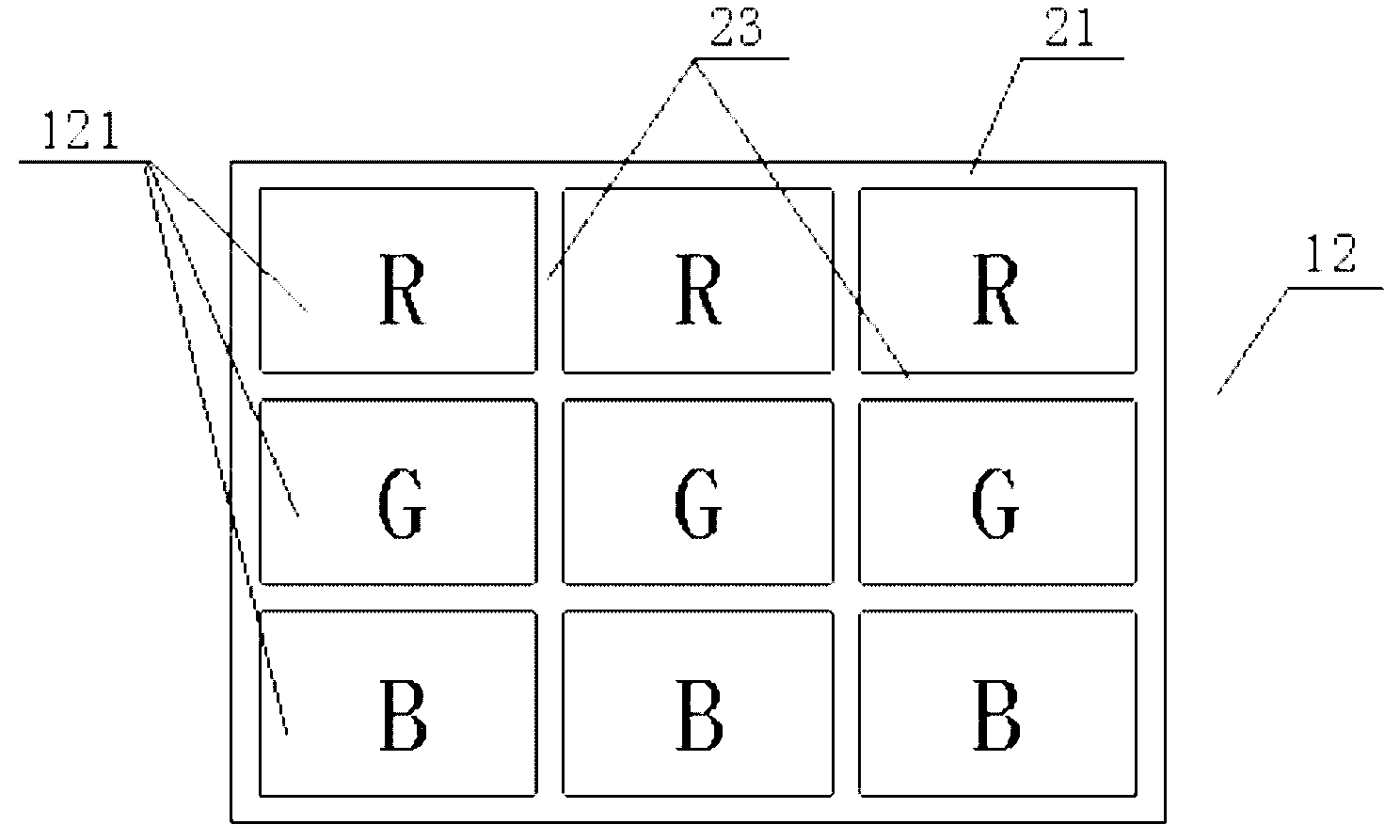
[0078] Implementation Mode Three: Refer to Figure 7 , the projection system only uses one laser CRT1, and one laser CRT1 can generate three parallel laser light sources, each of which is one of the three primary colors. The combination of three laser light sources through the optical prism group 4 forms a beam of three-color synthetic light. The above design effectively saves the number of laser CRTs and reduces the space and cost of the projection system. use Figure 7 When the laser CRT1 is shown, the laser CRT1 should have the following design: refer to image 3 , the laser panel 12 is provided with three rows of laser cavities 121, and the first row of laser cavities 121 uses red laser cavities 121 in the three primary colors, marked as R. The second row of laser cavities 121 adopts green laser cavities 121 in the three primary colors, marked as G. The third row of laser cavities 121 adopts the blue laser cavity 121 of the three primary colors, marked as B. A panel m...


PUM


Abstract

The invention relates to the technical field of electronics, in particular to a cathode ray tube (CRT) and a projection system. A low-power-consumption laser CRT based on a laminar flow electronic gun comprises a vacuum tube, wherein a laser panel is arranged at one end of the vacuum tube; the electronic gun is arranged at the other end of the vacuum tube; the electronic gun is the laminar flow electronic gun; the laminar flow electronic gun comprises a negative electrode, an electrode G1 and a control electrode; and the control electrode is connected with an electronic beam current control system. By adopting the technical scheme, the laminar flow electronic gun is used for emitting an electronic beam; the current density of the laser panel is relatively uniform, so that the power consumption of the laser panel is averaged; and energy converted into heat is reduced.

Description

technical field [0001] The invention relates to the field of electronic technology, in particular to a CRT and a projection system. Background technique [0002] With the rise of miniaturized and portable electronic devices, existing projection devices usually use handheld, low-power projection devices. The most suitable light source for this type of projection device is a laser light source or a light-emitting diode light source. Among them, the laser light source is widely regarded as a high-efficiency light source with low power consumption and high brightness. [0003] A projection system uses a light modulator to convert light emitted from a light source into an image frame. At present, such light modulators usually use liquid crystal projection / reflection liquid crystal displays, silicon-based liquid crystals, and digital micromirror devices in DLP technology. In order to display the image screen, lasers with three primary colors of green / blue / red are needed. [000...

Claims


Application Information

Patent Timeline
Patent Type & Authority Applications(China)
IPC IPC(8): H01J29/48H01J31/10G02B27/18G02B27/48G03B21/20
CPCG03B21/2033G02B27/18H01J29/481H01J31/10G02B27/48H01J29/48
Inventor 赵健严瑗张学渊钟伟杰夏忠平
Owner SHANGHAI FOREALIGHT SCI & TECH
Why Eureka
Try Eureka