Enzyme biological fuel cell and preparing method thereof

A biofuel cell and electrode technology, applied in the direction of biochemical fuel cells, etc., can solve problems such as instability and unfavorable operation of biofuel cells for a long time, and achieve good stability

Inactive Publication Date: 2012-07-11
NANJING UNIV
View PDF2 Cites 20 Cited by
  • Summary
  • Abstract
  • Description
  • Claims
  • Application Information

AI Technical Summary

Problems solved by technology

However, the introduction of the intermediary has also brought some problems, mainly because it is usually unstable, which is unfavorable for the long-term operation of the biofuel cell [see: (a) M.J.Moehlenbrock, S.D.Minteer, Chem.Soc.Rev. 2008, 37, 1188-1196; (b) S.K. Chaudhuri, D.R. Lovley, Nat. Biotechnol. 2003, 21, 1229-1232.]

Method used


Image

  • Enzyme biological fuel cell and preparing method thereof
  • Enzyme biological fuel cell and preparing method thereof
  • Enzyme biological fuel cell and preparing method thereof

Examples


Embodiment 1

[0021] Example 1. Construction of Yin and Yang poles in enzyme biofuel cell

[0022] The base electrode used in the enzyme biofuel cell constructed in the experiment is a gold sheet electrode (1cm × 0.5cm), provided by 55 Institute (Nanjing, China). Before use, the gold sheet substrate was polished with absorbent cotton. Then ultrasonic cleaning was performed with ethanol and ultrapure water respectively, and finally blow-dried under nitrogen flow.

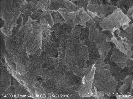
[0023] The preparation of the bioanode was similar to that reported in previous literature [Ref: Y.Chen, Y.Li, D.Sun, D.Tian, ​​J.Zhang, J.-J.Zhu, J.Mater.Chem 2011, 21, 7604-7611.]. The optimal experimental conditions for biocathode preparation are as follows: first, 50 μL (0.75 mg mL -1 ) of the graphene-nano-gold composite solution was dropped onto the gold sheet electrode, and then the gold sheet electrode was dried at a constant temperature of 37°C. After preparing the graphene-nanogold composite electrode, 50 μL laccase s...

Embodiment 2

[0024] Example 2. Construction of Enzyme Biofuel Cell

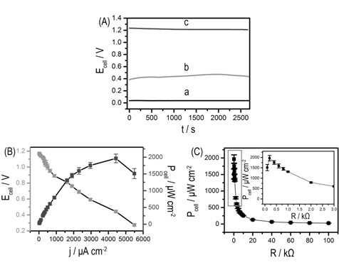
[0025] Perfluorosulfonic acid / PTFE copolymer diaphragm (DuPont TM PFSA NRE-211, with a thickness of 25.4 μm) as a separator between the cathode and anode of a biofuel cell. The anolyte was nitrogen saturated acetate buffer (0.2 M, pH 5.0) containing 50 mM glucose. The catholyte was acetate buffer (0.2M, pH 5.0) containing 0.5mM ABTS, which required saturation with oxygen. When testing the power output curve, when the enzyme biofuel cell obtains a stable open circuit potential, various load values ​​(100Ω~100kΩ) are connected to the two poles of the battery, and a digital multimeter is used to measure the power output on the load. The open circuit potential, polarization curve, power density curve and the relationship between power density curve and external resistance of enzyme biofuel cells are shown in image 3 , the red and yellow light-emitting diodes of the two enzyme biofuel cells were successfully lit, and the...

Embodiment 3

[0026] Example 3. Construction of Enzyme Biofuel Cell

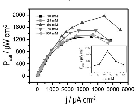
[0027] Build enzyme biofuel cell by the step of embodiment 2, but the concentration of glucose is 10mM, the open circuit potential that obtains, polarization curve and power density curve will be lower than the result of embodiment 2, see figure 2 .


PUM

PropertyMeasurementUnit
electric potential / voltageaaaaaaaaaa
thicknessaaaaaaaaaa
internal resistanceaaaaaaaaaa

Abstract

An enzyme biological fuel cell is prepared by the steps of separating a negative pole and a positive pole by phenol proton exchange membrane (DuPontTMPFSA NRE-211), preparing substrate materials of the negative pole and the positive pole to be grapheme-nanu-au composition, respectively loading laccase and glucose oxidase on substrate materials, using the loaded laccase and glucose oxidase to catalyze respectively oxygen and glucose substrate in a cathode chamber and an anode chamber to receive and lose electrons, and forming a loop by the fact that electrons start from the anode, pass through an external circuit and reach the cathode. When glucose concentration of the enzyme biological fuel cell in the anode chamber is 50 mM, open-circuit voltage of the cell is 1.2V, maximum power density of the cell is 1.96+-0.13mW cm-2, and internal resistance of the cell is only 200 omega. Two enzymebiological fuel cells connected in series can light a red or a yellow luminous diode successively. After the enzyme biologica fuel cell is assembled for 70 days, open circuit potential of the cell remains 80% of the best value. The preparing method is also disclosed.

Description

technical field [0001] The present invention relates to enzyme biofuel cells. Background technique [0002] With the depletion of traditional non-renewable energy sources, in today's society, researchers are trying their best to find an effective way to convert chemical energy into electrical energy, thereby alleviating the pressure of increasing energy consumption [see: M.J.Moehlenbrock, S.D.Minteer, Chem.Soc.Rev.2008, 37, 1188-1196.]. Harvesting energy from the environment to drive electronic devices has always been a human dream [See: C.Pan, Y.Fang, H.Wu, M.Ahmad, Z.Luo, Q.Li, J.Xie, X.Yan , L. Wu, Z. L. Wang, J. Zhu, Adv. Mater. 2010, 22, 5388-5392.]. In the 1980s and early 1990s, the fascinating "biofuel cells" began to enter the research stage, with the goal of building "green", sustainable [cf.: (a) T.K.Tam, G.Strack, M .Pita, E.Katz, J.Am.Chem.Soc.2009, 131, 11670-11671; (b) V.Coman, C.Vaz-Dominguez, R.Ludwig, W.Herreither, D.Haltrich, A.L.De Lacey, T.Ruzgas, L.G...

Claims


Application Information

Patent Timeline
Patent Type & Authority Applications(China)
IPC IPC(8): H01M8/16
CPCY02E60/527Y02E60/50
Inventor 张剑荣陈云
Owner NANJING UNIV
Why Eureka
Try Eureka