Aerodynamic engine assembly

An aerodynamic and engine technology, applied in electric vehicles, electrical components, exhaust devices, etc., can solve the problems of low utilization rate of gas distribution devices and energy, insufficient utilization of compressed air, failure to achieve energy saving, etc., to achieve maximum utilization High efficiency, low cost, and work-saving effects

Active Publication Date: 2012-07-18
周国泰 +1
View PDF4 Cites 7 Cited by
  • Summary
  • Abstract
  • Description
  • Claims
  • Application Information

AI Technical Summary

Problems solved by technology

[0003] In the process of searching for new energy sources, it has been found that the thrust generated when compressed air is released can be used as a power source, and then its thrust can be converted into mechanical energy or electrical energy. Some devices that use compressed air to obtain power have been disclosed. For example, turbo-type compressed air-powered engines and piston-type compressed-air engines have relatively low gas distribution devices and energy utilization; there is also a "gas-electric hybrid engine", which uses electric energy and compressed air to generate energy. The thrust is integrated to obtain energy. The generator used by this engine still needs to be driven by external energy, which indirectly uses external energy, so the purpose of energy saving cannot be achieved. In addition, the compressed air in this engine is directly discharged after doing work, and the compressed air after discharge is not fully utilized. , resulting in a waste of energy

Method used


Image

  • Aerodynamic engine assembly
  • Aerodynamic engine assembly
  • Aerodynamic engine assembly

Examples


Embodiment Construction

[0039] In order to further understand the invention content, characteristics and effects of the present invention, the following examples are given, and detailed descriptions are as follows in conjunction with the accompanying drawings:

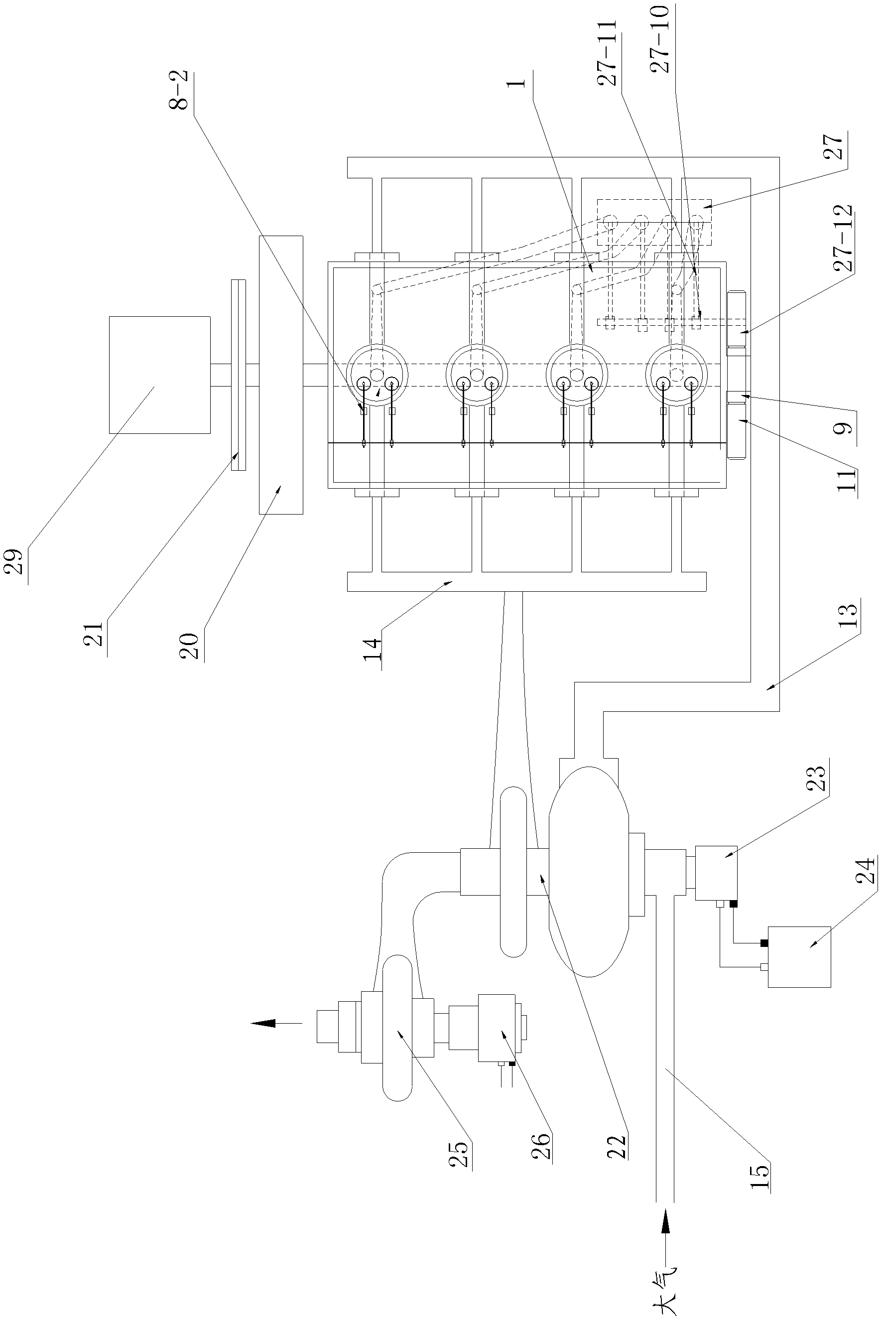
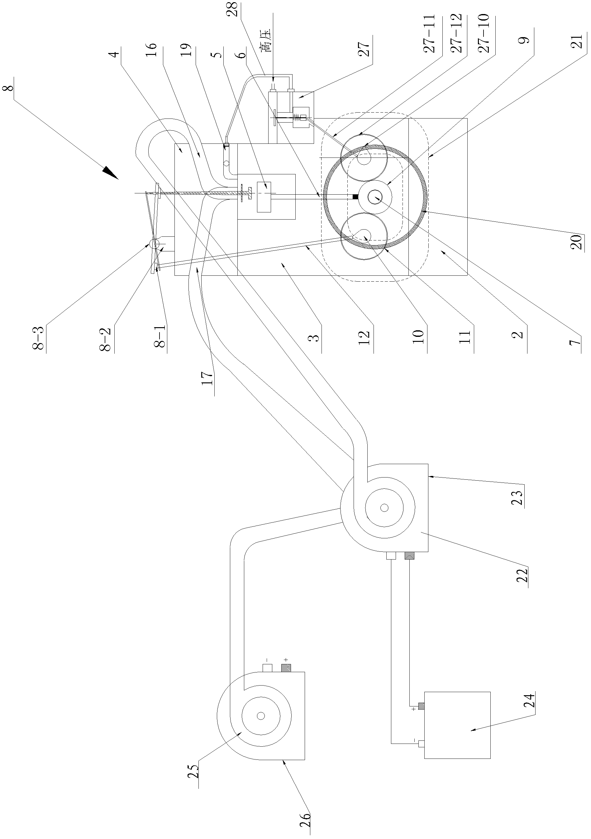
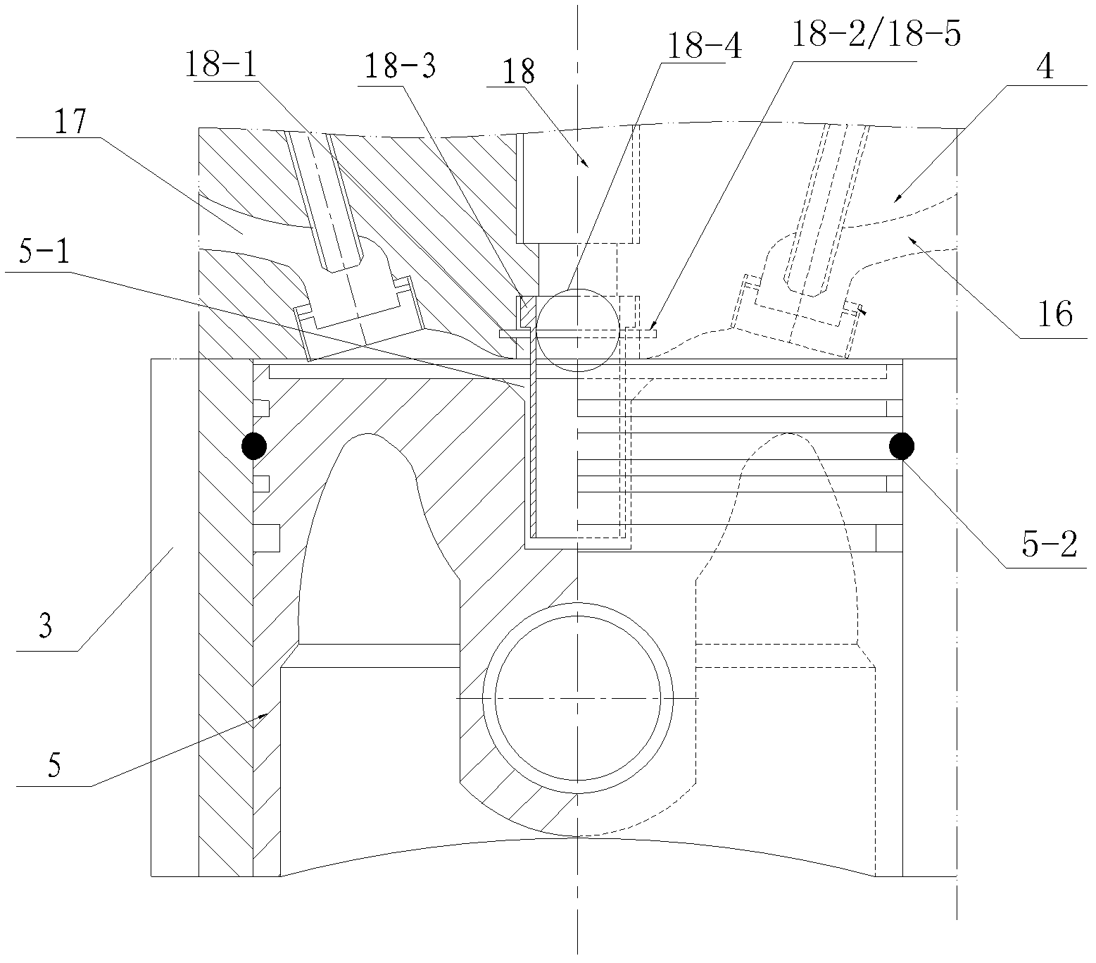
[0040] see figure 1 and figure 2 , an aerodynamic engine assembly, comprising an engine case 1, a bottom case 2, a cylinder block 3, a cylinder head 4, a piston 5 and a connecting rod 6 installed in the cylinder body, a crankshaft 7, and a valve assembly 8, on which the crankshaft 7 is installed Crankshaft timing gear 9 is arranged, and crankshaft timing gear 9 meshes with the timing gear 11 installed on the camshaft 10, and the camshaft 10 is installed on the engine housing 1, and the cam of the camshaft 10 is hinged with a push rod 12. The upper part of the ejector rod 12 is connected to the valve assembly 8, the valve assembly 8 mainly includes the rocker back 8-1 connected to the ejector rod 12, and the rocker back 8-1 is installed on t...


PUM


Abstract

The invention relates to an aerodynamic engine assembly, which belongs to the technical field of aerodynamics and comprises an engine shell, a bottom shell, a cylinder body, a cylinder cover, a crankshaft, a flywheel, a clutch and a speed changing box. A valve component is disposed on the cylinder cover, the cylinder cover is provided with an air inlet channel and an air exhaust channel, the air inlet channel and the air exhaust channel are connected with an air inlet header pipe and an air exhaust header pipe, a high-pressure air inlet channel is further disposed on the cylinder cover, a one-way valve is disposed in the high-pressure air inlet channel, and the high-pressure air inlet channel is connected with a high-pressure controller via a high-pressure air source controlling device. The aerodynamic engine assembly is characterized in that a turbocharger is mounted between the air inlet header pipe and the air exhaust header pipe, an air inlet end of the turbocharger is connected with the atmosphere, the turbocharger is connected with a power generator, the power generator is connected with a storage battery, and a turbine generator set which is in step layout is mounted on a tail gas exhaust tube of the turbocharger and is connected with the storage battery. In conclusion, the aerodynamic engine assembly has the advantages of simple structure, reasonable design, capabilities of controlling high-pressure air sources to supply air uniformly, supplementing air pressure loss and saving energy, and the like.

Description

technical field [0001] The invention belongs to the field of engine manufacturing, in particular to an aerodynamic engine assembly using compressed air as a power source. Background technique [0002] Engines are widely used in various industries, and generally piston internal combustion engines are mainly used, and these engines use fuel oil as a power source. On the one hand, the engine using fuel oil as the power source pollutes the environment due to insufficient fuel combustion, which makes the exhaust gas contain a large amount of harmful substances, and on the other hand, the fuel used is extracted from petroleum. As we all know, oil is a non-renewable energy source on the earth. Therefore, with the massive exploitation and use of people, oil reserves are getting less and less. Therefore, it is necessary to develop new, clean, and pollution-free energy sources, especially new energy sources that are inexhaustible. [0003] In the process of searching for new energy s...

Claims


Application Information

Patent Timeline
Patent Type & Authority Applications(China)
IPC IPC(8): F01B25/02F01B25/08F01N5/04F04D25/08F01D15/10H02J7/32
CPCY02T10/16Y02T10/12
Inventor 周国泰朱仕亮
Owner 周国泰
Why Eureka
Try Eureka