Laser ultrasonic detection method for micro defects

A technology of laser ultrasound and detection method, applied in the direction of optical testing flaws/defects, scattering characteristics measurement, etc., can solve the problems of poor detection accuracy, bulky, affecting the detection effect, etc., to overcome the influence of blind spots, high detection sensitivity, detection simple craftsmanship

Inactive Publication Date: 2012-07-25
SHANGHAI INST OF SPECIAL EQUIP INSPECTION & TECHN RES
View PDF3 Cites 10 Cited by
  • Summary
  • Abstract
  • Description
  • Claims
  • Application Information

AI Technical Summary

Problems solved by technology

However, this method is limited by the principle. The ultrasonic waves emitted by the transmitting probe are greatly attenuated in the air, the energy transmitted to the workpiece is very low, and the signal received by the receiving probe is very small, which affects the detection effect.
[0004] To sum up, the electromagnetic ultrasonic testing method (EMAT) can only detect the environment with relatively large volume and no noise pollution, and cannot detect non-conductive materials.
The laser ultrasonic detection method (Laser) itself is complex, bulky, expensive, difficult and inconvenient to adjust and other factors affect its application
The air-coupled ultrasonic testing method (ACUT) is limited by the principle, the ultrasonic wave is attenuated in the air twice, and the detection effect is not good
In addition, electromagnetic and air ultrasonic testing methods have poor detection accuracy and are difficult to detect micro-defects
Therefore, the above methods have many deficiencies in solving micro-defects near the surface (or thinner workpieces) in some special environments.

Method used


Image

  • Laser ultrasonic detection method for micro defects
  • Laser ultrasonic detection method for micro defects
  • Laser ultrasonic detection method for micro defects

Examples


Embodiment 1

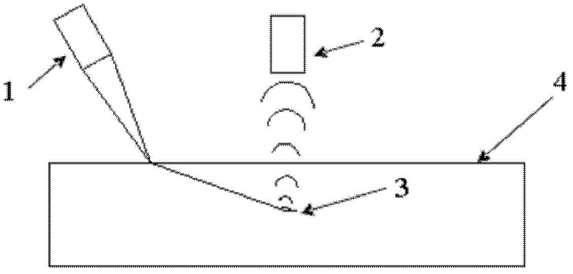
[0025] 1. Select an aluminum alloy sheet workpiece in a factory, with a specification of 100mm×80mm×6mm, and place the aluminum alloy sheet workpiece on figure 1 In the environment, with figure 1 way to detect.

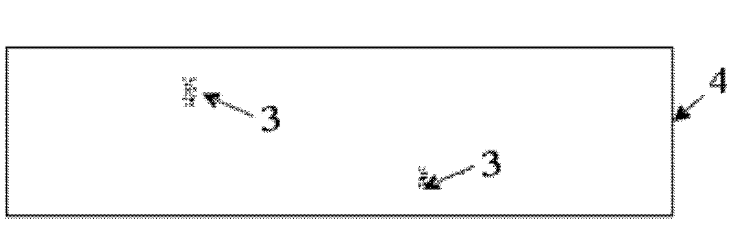
[0026] 2. Adjust the laser probe 1 so that the laser emitted by the laser probe 1 acts on the workpiece 4 to generate ultrasonic waves. When the ultrasonic waves generated in the process 4 meet the defects 3 in the material, a new wave source is formed. The new wave source As a secondary wave source, "scattered waves" are emitted in all directions, and the air-coupled probe 2 is vertically aligned with the workpiece 4, and the two probes are moved synchronously on the same side of the thin plate on the fixed frame.

[0027] 3. Adjust CH1 on the oscilloscope to 500mvΩ, and M to 1.00us. Observe the radio frequency signal on the oscilloscope. When a radio frequency signal wave appears on the oscilloscope, the air-coupled probe receives a radio frequency signal wave. Th...

Embodiment 2

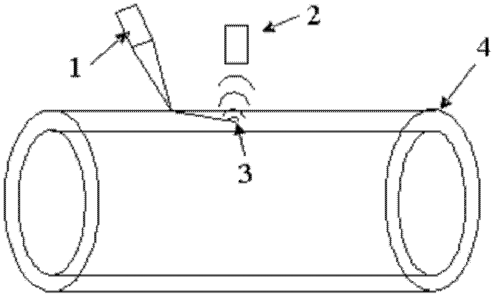
[0030] 1. Select a high-temperature pipe fitting in service in a heating network company, the specification is ¢100×8mm, the pipe temperature is 250°C, and the high-temperature pipe fitting is placed in the image 3 In the environment, with image 3 way to detect.

[0031] 2. Adjust the laser probe 1 so that the laser emitted by the laser probe 1 acts on the pipe 4 to generate ultrasonic waves. When the ultrasonic waves generated in the pipe 4 encounter the defect 3 in the material, a new wave source is formed, and the new wave source is regarded as The secondary wave source emits "scattered waves" in all directions, and the air-coupled probe 2 is aligned vertically with the pipe 4, 10mm away from the surface of the pipe 4, and the two probes are moved synchronously on the same side of the pipe on the fixed frame.

[0032] 3. Adjust CH1 on the oscilloscope to 500mvΩ, and M to 1.00us. Observe the radio frequency signal on the oscilloscope. When the air-coupled probe receives ...


PUM

PropertyMeasurementUnit
thicknessaaaaaaaaaa

Abstract

The invention relates to a laser ultrasonic detection method for micro defects. The method comprises the following steps of: obliquely acting pulse laser emitted by a laser probe on a detected workpiece; placing an air coupling probe on the same side of the laser probe, ensuring that the air coupling probe is vertically opposite to the surface of the detected workpiece, and adjusting the distance between the air coupling probe and the surface of the detected workpiece to receive scattered signals generated by the defects of a material; and judging the existence of the defects in the material through the scattered signals received by the air coupling probe. The method can be used for overcoming the influence of a blind area, is suitable for detecting the defects of thin workpieces and near surfaces, and is simple in detection process; the detection process is controlled by a machine; and the method is good in repeatability, and does not depend on the technical level and working attitude of detection personnel.

Description

technical field [0001] The invention relates to the technical field of nondestructive testing, in particular to a laser ultrasonic testing method for micro-defects and near-surface defects of workpieces in special environments. Background technique [0002] With the development of society, the improvement of productivity level, the improvement of infrastructure, the detection of steel on-line production in high temperature environment, the high-speed detection of train tracks and oil pipelines, and the detection of equipment with complex surface conditions, etc., the demand for non-destructive testing is increasing. At the same time, these complex testing conditions also pose challenges to traditional nondestructive testing methods. Effective evaluation of non-destructive testing is of great significance for improving manufacturing processes, improving product quality, ensuring life safety, and ensuring reliable operation of equipment. Conventional non-destructive testing m...

Claims


Application Information

Patent Timeline
Patent Type & Authority Applications(China)
IPC IPC(8): G01N21/88G01N21/49
Inventor 王继锋王少军俞厚德钱耀洲汤晓英
Owner SHANGHAI INST OF SPECIAL EQUIP INSPECTION & TECHN RES
Why Eureka
Try Eureka