
Cyclone burner and air burnout arrangement structure for boiler

A swirl burner, the technology of arrangement structure, which is applied in the direction of burning with multiple fuels, burning with block fuel and liquid fuel, burning with block fuel and gaseous fuel, etc. Corrosion, low boiler combustion efficiency, etc., to reduce high-temperature corrosion and slagging, improve operating efficiency, and increase residence time

Inactive Publication Date: 2012-08-01
HARBIN INST OF TECH
View PDF6 Cites 9 Cited by
  • Summary
  • Abstract
  • Description
  • Claims
  • Application Information

AI Technical Summary

Problems solved by technology

[0004] In order to solve the problem of low boiler combustion efficiency in the existing exhaust air arrangement structure of the swirl burner arranged on the front wall, and at the same time exacerbate the problems of slagging and high-temperature corrosion on the rear wall, the present invention further provides a swirl burner for the boiler and overfire air arrangement

Method used


Image

  • Cyclone burner and air burnout arrangement structure for boiler
  • Cyclone burner and air burnout arrangement structure for boiler
  • Cyclone burner and air burnout arrangement structure for boiler

Examples


specific Embodiment approach 1

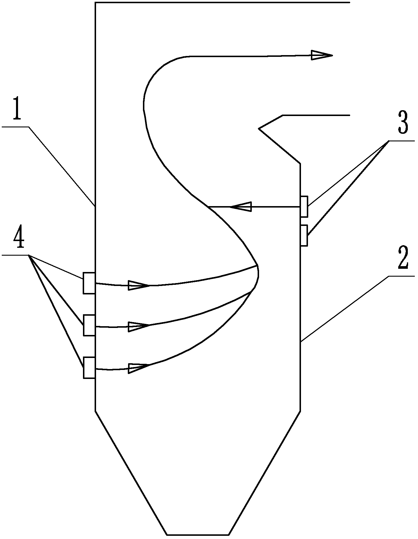
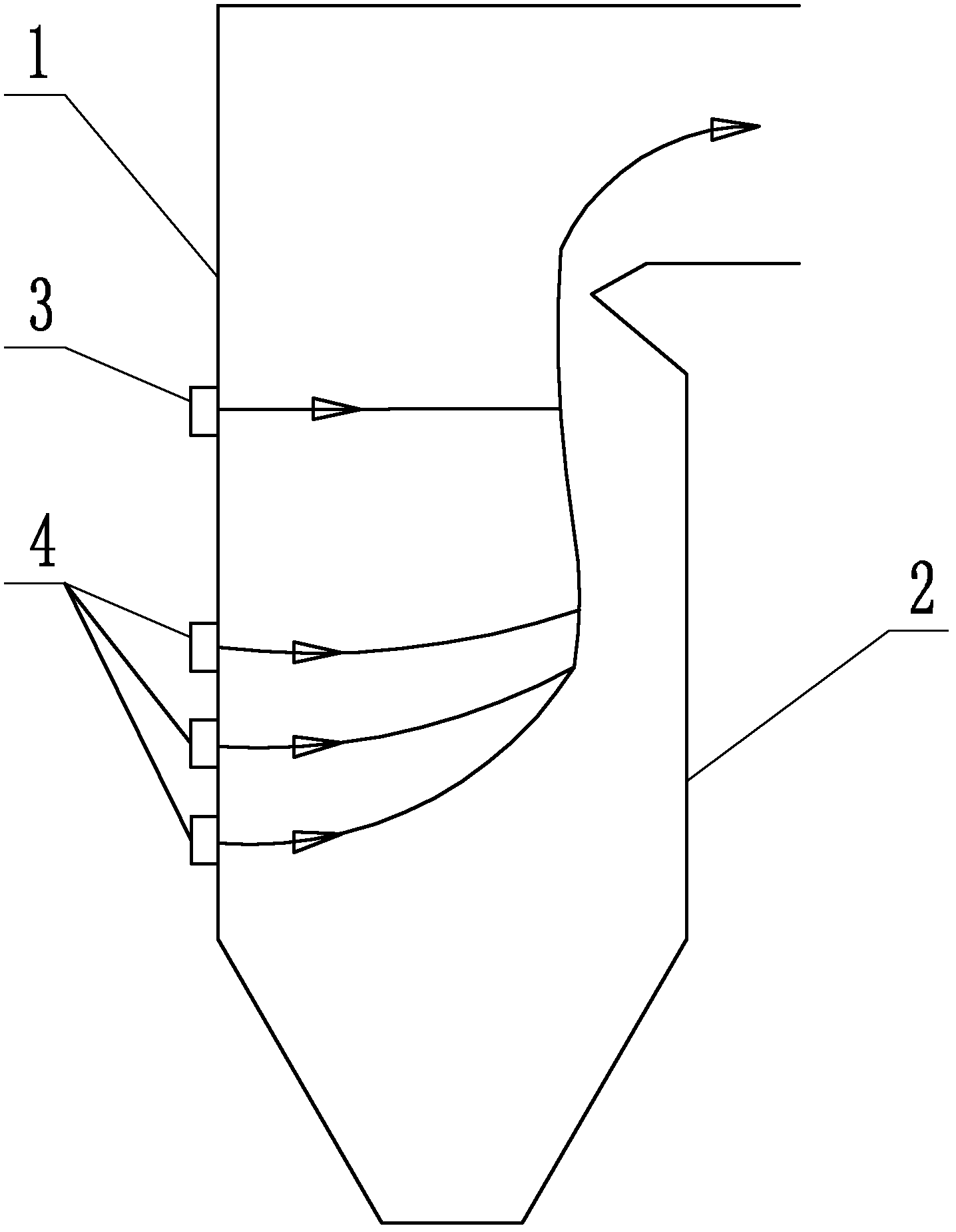
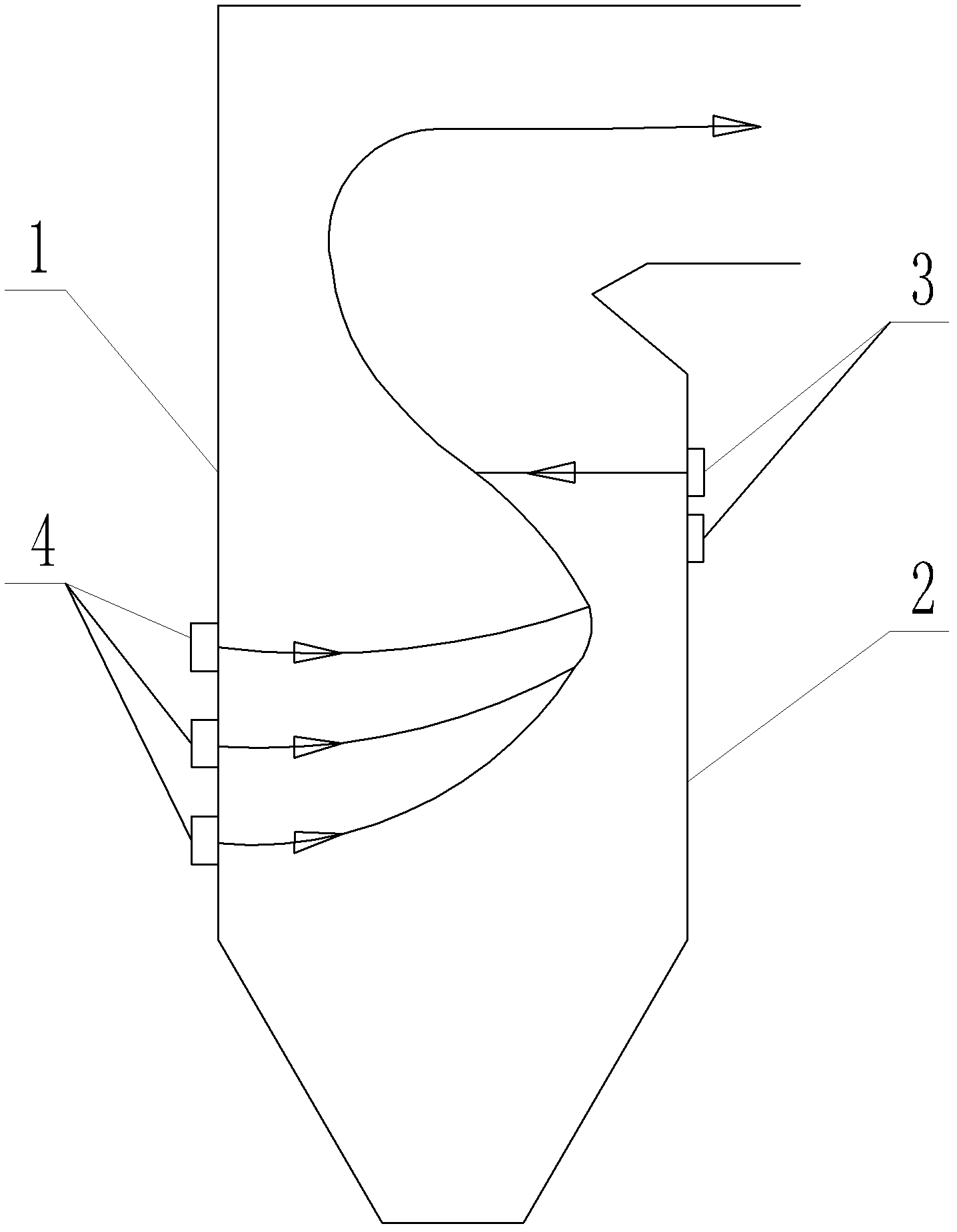
[0011] Specific implementation mode one: combine figure 1 Explain that the arrangement structure of the boiler's swirl burner and overfired air in this embodiment includes at least one layer of overfired air nozzle 3 and three layers of swirl burners 4, and the swirl burner 4 is arranged on the front wall 1 of the boiler. The overfire air nozzle 3 is arranged on the rear wall 2 of the boiler and is located above the side of the swirl burner 4 .

specific Embodiment approach 2

[0012] Specific implementation mode two: combination figure 1 Note that the number of the overburning air nozzle 3 in this embodiment is one. Such a design can prevent high-temperature corrosion of flue gas, increase flue gas travel, increase the residence time of combustibles in the furnace, effectively reduce the carbon content of boiler fly ash, and improve boiler operating efficiency. Other compositions and connections are the same as those in Embodiment 1.

specific Embodiment approach 3

[0013] Specific implementation mode three: combination figure 1 Note that the number of overburning air nozzles 3 in this embodiment is two. With this design, the overfired air enters the furnace in two stages, and the air volume of each layer of overburned air can be adjusted during operation to facilitate the adjustment of the combustion of combustibles in the furnace. Other compositions and connections are the same as those in Embodiment 1.


PUM


Abstract

A cyclone burner and an air burnout arrangement structure for a boiler relate to cyclone burners and air burnout arrangement structures, and solve the problems of low boiler combustion efficiency and intensification of rear wall slagging and high temperature corrosion of an existing air burnout arrangement structure with the cyclone burner arranged on a front wall. An air burnout spout is arranged on the rear wall of the boiler and positioned laterally above the cyclone burner. The cyclone burner and the air burnout arrangement structure for the boiler are used for reducing unburned carbon in flue dust of the boiler and improve operating efficiency of the boiler.

Description

technical field [0001] The invention relates to a swirl burner and an arrangement structure of overfired air. Background technique [0002] 67% of my country's nitrogen oxide emissions come from coal burning, nitrogen oxides in the atmosphere include NO, NO 2 , N 2 O, N 2 o 3 , N 2 o 4 , N 2 o 5 etc., usually collectively referred to as NO x , NO x It is one of the main sources of air pollution. Nitrogen oxides from the combustion of fossil fuels account for a large proportion of all nitrogen oxide emissions worldwide each year. With the improvement of environmental protection requirements, the country's NO x Emissions controls are getting stricter. NO x The control technology is mainly divided into three categories, one is the use of air classification technology in the furnace, the other is the use of low nitrogen oxide burners, and the third is the use of tail denitrification technology. Adopting flue gas denitrification technology requires a large initial i...

Claims


Application Information

Patent Timeline
Patent Type & Authority Applications(China)
IPC IPC(8): F23C5/32F23C7/02
Inventor 曾令艳李争起陈智超张宏宇张翔周航王阳赖金平
Owner HARBIN INST OF TECH
Learn More