
High-power laser beam sampler and high-power laser beam measuring system

A laser beam and high-power technology, which is applied in the field of high-power laser beam sampler and high-power laser beam measurement system, can solve the problems of difficult application of high-power and high-energy laser, poor ability to withstand laser irradiation, etc., to improve Effects of resisting laser damage threshold, reducing angle sensitivity, and expanding application range

Active Publication Date: 2012-08-01
NORTHWEST INST OF NUCLEAR TECH
View PDF6 Cites 4 Cited by
  • Summary
  • Abstract
  • Description
  • Claims
  • Application Information

AI Technical Summary

Problems solved by technology

[0004] The technical problem to be solved by the present invention is to provide a high-power laser sampling and measurement based on optical fiber array for the existing photoelectric array detection method, which has poor ability to withstand laser irradiation and is difficult to apply to high-power and high-energy laser measurement. method

Method used


Image

  • High-power laser beam sampler and high-power laser beam measuring system
  • High-power laser beam sampler and high-power laser beam measuring system
  • High-power laser beam sampler and high-power laser beam measuring system

Examples


Embodiment Construction

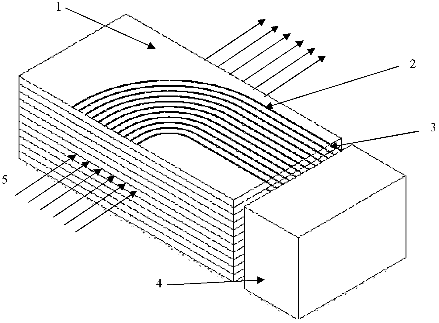
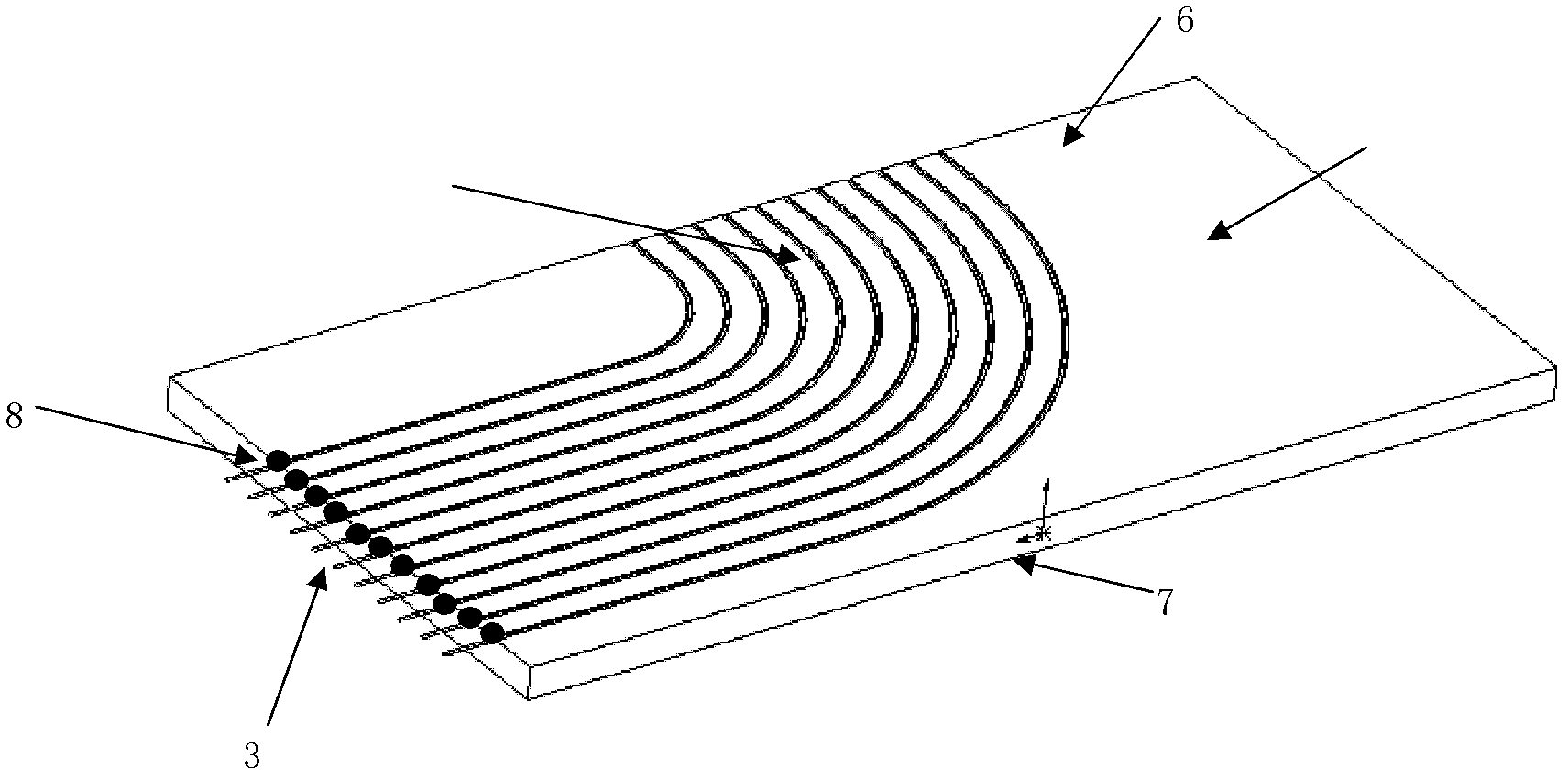
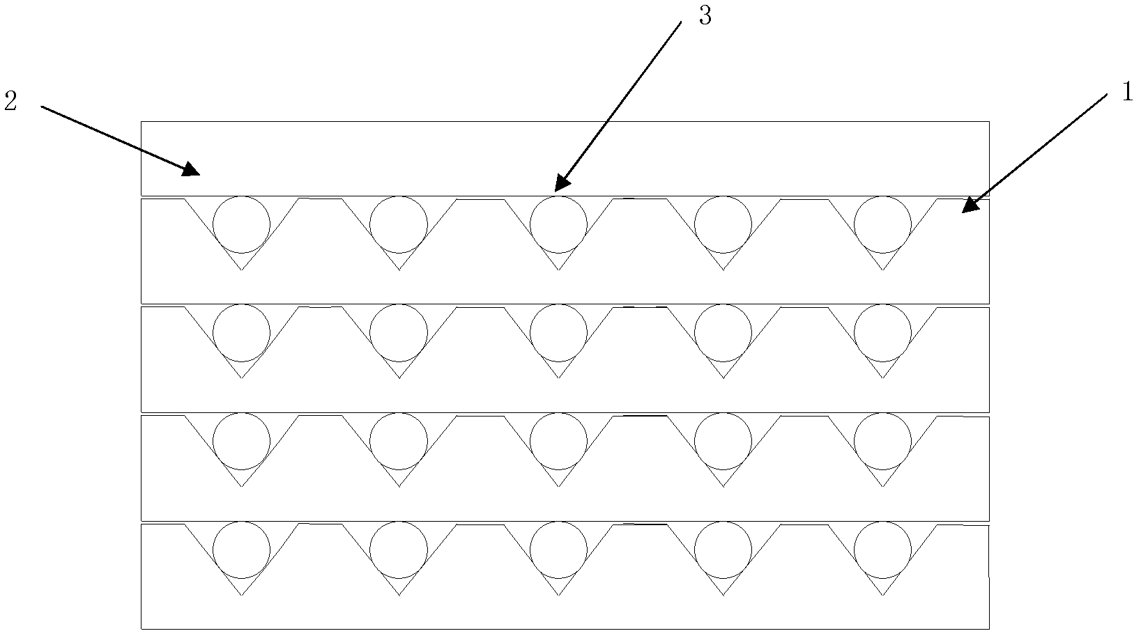
[0028] Such as figure 1 As shown, the high-power laser beam sampler includes a plurality of sampling optical fibers 3 and a plurality of dielectric plates 1 arranged in parallel and stacked along the incident direction of the laser light. One surface of the dielectric plate 1 is a scoring surface 6. First, each surface of the plate is After polishing, the size of the L-shaped groove 2 is designed according to the size of the optical fiber 3, and the L-shaped groove is carved on the flat polishing surface. The cross-section in the L-shaped groove can be V-shaped, U-shaped or other shapes, L One side of the L-shaped groove is in the same direction as the incident laser beam, and the other side is perpendicular to the incident direction of the laser beam. There is a circular arc transition between the two sides. The distance between the L-shaped groove and the circular arc transition fillet depends on the space to be achieved by the sampler. The resolution depends on the specific...


PUM


Abstract

The invention discloses a high-power laser beam sampler and a high-power laser beam measuring system. The sampler comprises a plurality of optical fibers and laminated dielectric slabs, a plurality of parallel L-shaped groove arrays are arranged on the dielectric slabs, the optical fibers are arranged in L-shaped grooves, and an optical fiber incidence end faces a laser incidence direction, and an output end deviates from laser beams. The measuring system comprises the high-power laser beam sampler, a plurality of detectors, a signal processing circuit and a data acquisition processing unit. In the measuring system, by means of overlapping and clamping the optical fibers through the dielectric slabs, damage to the sampler caused by laser absorption of organic matters such as coating materials, glue or the like is avoided, and the threshold value of laser damage resistance of the sampler is improved. Besides, in application, the vast majority of laser is transmitted, only small parts of beams are sampled, the requirement of the system on bearing laser irradiation is lowered, and subsequent beams can be reused.

Description

technical field [0001] The invention relates to a high-power laser beam sampler and a high-power laser beam measurement system, in particular to a sampler and a measurement system for sampling and measuring high-power lasers using an optical fiber array. Background technique [0002] The output power of high-power lasers is as high as tens of thousands or hundreds of thousands of watts, and the diameter of its far-field beam can reach tens of centimeters. Due to its strong destructive power, the measurement of light intensity distribution parameters has become a technical problem. Commonly used high-power laser intensity spatio-temporal distribution measurement methods mainly include mechanical scanning sampling method and photoelectric array detection method. In 2001, the Chinese patent ZL02114633.0 invented a high-power laser beam measurement sampler based on the mechanical scanning sampling method. The ring light reflector is used to reflect the laser beam to the detector...

Claims


Application Information

Patent Timeline
Patent Type & Authority Applications(China)
IPC IPC(8): G01J1/04G01J1/00
Inventor 吴勇杨鹏翎陈绍武王平王振宝武俊杰刘福华冯国斌叶锡生
Owner NORTHWEST INST OF NUCLEAR TECH
Learn More