Sludge drying and incinerating integrated treatment system and process thereof

A sludge drying and sludge incineration technology, applied in the field of sludge treatment system and its process, can solve the problems of energy loss, high processing energy consumption, poor economy of sludge drying and incineration treatment process route, etc.

Active Publication Date: 2012-08-15
ZHEJIANG UNIV
View PDF6 Cites 19 Cited by
  • Summary
  • Abstract
  • Description
  • Claims
  • Application Information

AI Technical Summary

Problems solved by technology

The high-temperature flue gas produced by sludge incineration is generally subjected to dust removal, desulfurization, and denitrification after heat exchange by an air preheater. The heat in the high-temperature flue gas has not been effectively utilized, resulting in a large amount of energy loss
[00

Method used


Image

  • Sludge drying and incinerating integrated treatment system and process thereof
  • Sludge drying and incinerating integrated treatment system and process thereof

Examples


Embodiment Construction

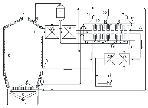
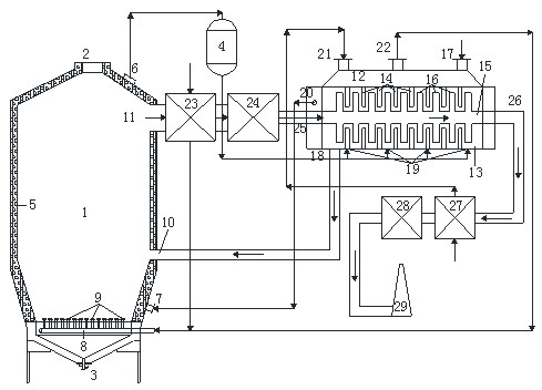
[0017] Such as figure 1 As shown, the sludge drying and incineration integrated treatment system includes a sludge incinerator 1, a steam drum 4, a sludge drying unit 12, an air preheater 23, a dust collector 24, a carrier gas preheater 27, and a desulfurization unit 28 And chimney 29, sludge incinerator 1 includes flue gas explosion-proof door 2, slag discharge port 3, membrane water wall 5, steam outlet 6, circulating water inlet 7, air distribution plate 8, air cap 9, dry sludge feeding port 10 , the flue gas outlet 11, the sludge drying unit 12 includes an outer wall 13, a fixed paddle 14, a hollow shaft 15, a rotating paddle 16, a wet sludge inlet 17, a dried sludge outlet 18, and a steam heat source inlet 19. Steam heat source outlet 20, carrier gas inlet 21, drying exhaust gas outlet 22, flue gas heat source inlet 25, flue gas heat source outlet 26;

[0018] Sludge incinerator 1. Membrane water wall 5 is installed on the furnace wall, flue gas explosion-proof door 2 is...


PUM


Abstract

The invention discloses a sludge drying and incinerating integrated treatment system and a process thereof. A sludge incinerator is formed by externally laying a fire resistant material on a membrane wall; through the high-temperature smoke generated by sludge incineration, a part of heat is transferred to the membrane wall to generate steam which serves as a heat source together with the discharged smoke so as to dry the sludge; a sludge drying unit mainly consist of a hollow rotation shaft, a rotatable blade which is arranged on the shaft, a hollow outer wall and a fixed blade which is arranged on the hollow outer water; smoke and steam are used together for heat exchange; the hollow rotation shaft is arranged on a sludge incineration smoke pipe, serves as a part of the smoke pipe and asmoke heat source flows in the hollow rotation shaft; a steam heat source flows in the hollow outer wall; and after transferring heat to the sludge, the smoke heat source is treated to reach the emission standard and then is emitted. According to the sludge drying and incinerating integrated treatment system and the process thereof, the sludge drying and incinerating processes are closely integrated, the energies of various heat carriers in the sludge drying and incinerating processes are fully utilized, the system energy consumption is greatly reduced and good economical efficiency is provided.

Description

technical field [0001] The invention relates to a sludge treatment system and a process thereof, in particular to a sludge drying and incineration integrated treatment system and a process thereof. Background technique [0002] The moisture content of the concentrated sludge produced by the sewage treatment plant can be as high as 99%. The mass and volume are huge, which is not conducive to transportation and treatment. It is necessary to reduce its moisture content. At present, most sewage treatment plants in my country only dehydrate the concentrated sludge produced, and the moisture content of the dewatered sludge is still about 80%, which still cannot meet the requirements for subsequent treatment and disposal such as sanitary landfill, composting or incineration. According to the research on the distribution characteristics of water in sludge, the water in sewage sludge can be divided into "free water", "interstitial water", "surface bound water" and "internal bound wat...

Claims


Application Information

Patent Timeline
IPC IPC(8): F23G7/00C02F11/12
Inventor 严建华王飞池涌李博陆胜勇黄群星李晓东蒋旭光马增益金余其薄拯倪明江岑可法
Owner ZHEJIANG UNIV
Why Eureka
Try Eureka