Micro-ring assistant ring mirror structure
A micro-ring and ring-mirror technology, used in light guides, optics, instruments, etc., can solve the problems of complex fabrication, unrealizable, unapplied wavelength selection, etc., to achieve a large wavelength tunable range, good process compatibility, increase wavelength The effect of (or frequency) adjustable function
- Summary
- Abstract
- Description
- Claims
- Application Information
AI Technical Summary
Problems solved by technology
Method used
Image
Examples
Embodiment 1
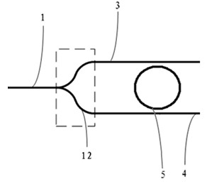
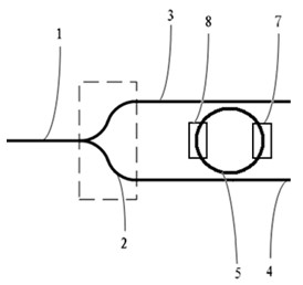
[0035] like figure 2 As shown, the device adopts a symmetrical Y branch structure 12 as a beam splitting coupling structure. The device is made of silicon-on-insulator (SOI) material, the thickness of the top silicon layer is 220 nm, and the thickness of the silicon dioxide buried layer is 1 μm. Using CMOS technology, through deep ultraviolet lithography and silicon dry etching, a ridge-shaped optical waveguide with a width of 400nm and a depth of 180nm is fabricated to form a figure 2 The device structure shown. The optical microring in the device is an optical waveguide ring with a radius of 5 μm. The gap between the microring and the two parallel waveguides is 180 nm. The Y branch structure is composed of S-shaped bends with a length of 25 μm.
[0036] After silicon dry etching is completed, a 1 μm silicon dioxide layer is covered by chemical vapor deposition. By sputtering, photolithography, and etching, the heating electrodes corresponding to the microrings are fab...
Embodiment 2
[0039] like Figure 4 As shown, the device uses a symmetrical X-cross junction structure 22 as the beam splitting coupling structure. The device is made of glass. Using buried ion exchange technology, a buried optical waveguide with a width of 10 μm and a depth of 18 μm is produced, forming Figure 4 The device structure shown. The optical microring in the device is a racetrack-shaped optical waveguide closed loop with a radius of 5mm. The gap between the microring and the two parallel waveguides is 3 μm. The widths of the asymmetric side waveguides of the X-cross junction structure are 8 μm and 12 μm, respectively, and the branch angle is 0.1 degree. The width of the symmetrical side waveguide is 10 μm, and the branch angle is 1 degree.
[0040] Thus, the auxiliary ring mirror with micro ring is completed. The ring mirror does not need to use the fine process required for Bragg grating production, has a reflectivity of 98%, and the Q value of the filter spectrum is great...
Embodiment 3
[0042] like Figure 5 As shown, the device uses a directional coupler structure 32 as a beam splitting coupling structure. The device is made of lithium niobate. Using titanium diffusion technology, a diffused optical waveguide with a width of 6 μm is produced to form a Figure 5 The device structure shown. The optical microring in the device is an optical waveguide ring with a radius of 500 μm. The gap between the microring and the two parallel waveguides is 2 μm. The waveguide gap of the directional coupler structure is 3 μm, and the length is 500 μm.
[0043] Thus, the auxiliary ring mirror with micro ring is completed. The ring mirror does not need to use the fine process required for Bragg grating production, has a reflectivity of 98%, and the Q value of the filter spectrum is greater than 1500.
PUM
 Abstract
Description
Claims
Application Information
 - R&D
- Intellectual Property
- Life Sciences
- Materials
- Tech Scout
- Unparalleled Data Quality
- Higher Quality Content
- 60% Fewer Hallucinations
Browse by: Latest US Patents, China's latest patents, Technical Efficacy Thesaurus, Application Domain, Technology Topic, Popular Technical Reports.
© 2025 PatSnap. All rights reserved.Legal|Privacy policy|Modern Slavery Act Transparency Statement|Sitemap|About US| Contact US: help@patsnap.com


