Device and method for controlling quality of laser beam

A laser beam quality and control device technology, applied in the field of technical lasers, can solve the problems that the fundamental mode Gaussian beam cannot be obtained, the practical application of the laser beam is affected, and the damage threshold is low

Active Publication Date: 2012-08-15
TSINGHUA UNIV
View PDF5 Cites 23 Cited by
  • Summary
  • Abstract
  • Description
  • Claims
  • Application Information

AI Technical Summary

Problems solved by technology

For example, the Chinese patent with the patent number "200910042404.6" uses a deformable mirror to compensate the wavefront of the laser to improve the beam quality of the laser, but the beam quality factor M 2 It can be seen from the definition that only compensating the wavefront can not get M 2 The fundamental mode of the Gaussian beam is 1, so this technology has certain limitations for improving the quality of the laser beam
[0012] In addition, the existing light intensity distribution control technology is projected attenuation, and will be limited by factors such as laser light intensity and aperture in practical applications.
For example, the Chinese patent with the patent number "02820338.0" proposes to directly use a mask with a certain light intensity distribution to change the intensity distribution of the beam for photolithography of semiconductor devices. This method needs to detect the intensity distribution of the laser, and then design, A mask corresponding to the transmittance distribution is processed to control the laser intensity distribution, but its design and processing cycle determine that this method cannot achieve real-time control of the laser. In addition, the damage threshold of this transmission mask is relatively low , which also limits its application to high power laser
For example, the Chinese patent with the patent number "01256697.7" mentions that the liquid crystal light valve is used to control the light intensity distribution of the laser. Although this method can effectively modulate the laser light intensity distribution in space, it can also use a closed-loop system to achieve automatic control. However, the splicing gap between the liquid crystal units will cause phase distortion of the wavefront of the laser beam. In severe cases, the wavefront of the laser beam will be cut, which will affect the practical application of the laser beam. In addition, the damage problem also restricts the application of the liquid crystal light valve in the laser light intensity space. A major factor in modulation

Method used


Image

  • Device and method for controlling quality of laser beam
  • Device and method for controlling quality of laser beam
  • Device and method for controlling quality of laser beam

Examples


Embodiment Construction

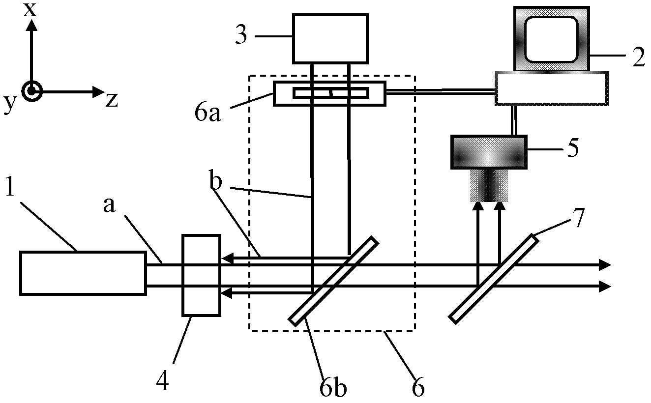
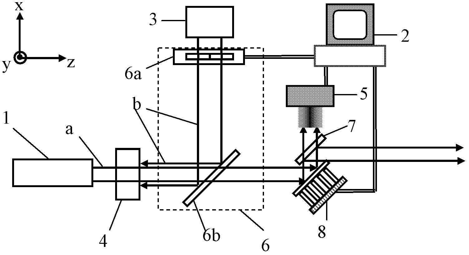
[0038] The specific implementation manners of the present invention will be further described in detail below in conjunction with the accompanying drawings and embodiments. The following examples are used to illustrate the present invention, but are not intended to limit the scope of the present invention.

[0039] like figure 1 , the control device of a kind of laser beam quality of the present invention comprises gain medium 4, pumping source 3, first optical element 6, second optical element 7, detector 5 and controller 2, and gain medium 4 is arranged on laser a On the optical path, the controller 2 is connected with the pumping source 3, and is used to control the pumping source 3 to emit pumping light b to the gain medium 4. The pumping light b enters the gaining medium 4 through the first optical element 6, and the laser light passes through the first optical element 6. After the optical element 6 is transmitted, it enters the second optical element 7. The second optic...


PUM


Abstract

The invention relates to the technical field of lasers, and discloses a device and method for controlling quality of a laser beam. The device comprises a gain medium, a pumping source, a first optical element, a second optical element, a detector and a controller, wherein the grain medium is arranged on a laser path, the controller is connected with the pumping source, pumping lights enters the gain medium through the first optical element, laser enters the second optical element after being transmitted by the first optical element, and the controller is connected with the first optical element and is used for controlling the first optical element to regulate the light intensity distribution of the pumping light. According to the invention, the grain medium is arranged on the laser path and can absorb the pumping light, and the controller controls the light intensity distribution of the pumping lights so regulate the light intensity distribution of the lasers, thus the quality of the laser beam is improved; furthermore, a laser wave front corrector is additionally arranged, and the phase distortion of the lasers can be compensated simultaneously so that the quality of the laser beam is further improved.

Description

technical field [0001] The invention relates to the technical field of laser technology, in particular to a control device and method for the quality of a laser beam. Background technique [0002] In practical applications, the beam quality of the laser is an important application parameter of the laser, which reflects the performance of laser focusing and propagation. For example, in the field of laser processing, a laser beam with good beam quality can make the focused beam spot smaller or the Rayleigh length (depth of focus) longer after focusing, thereby improving the laser's ability to process materials and obtaining better processing results. [0003] Laser beam quality factor M 2 Is the main parameter describing the quality of the laser beam, defined according to the ISO standard, M 2 It can be expressed as: [0004] M 2 = ωθ ω 0 ...

Claims


Application Information

Patent Timeline
Patent Type & Authority Applications(China)
IPC IPC(8): H01S3/131
Inventor 巩马理邱运涛柳强黄磊闫平张海涛刘欢
Owner TSINGHUA UNIV
Why Eureka
Try Eureka