Formation method of trench mos

A groove type and groove technology, which is applied in the manufacture of electrical components, semiconductor/solid-state devices, circuits, etc., can solve problems such as low process yield and poor electrical performance, and achieve improved electrical performance, uniform thickness, and breakdown voltage. The effect of increasing the value

Active Publication Date: 2016-04-06
SHANGHAI HUAHONG GRACE SEMICON MFG CORP
View PDF5 Cites 0 Cited by
  • Summary
  • Abstract
  • Description
  • Claims
  • Application Information

AI Technical Summary

Problems solved by technology

However, the electrical performance of the trench MOS formed by the existing process is poor, and the process yield is low

Method used


Image

  • Formation method of trench mos
  • Formation method of trench mos
  • Formation method of trench mos

Examples


Embodiment Construction

[0029] The electrical performance of the trench MOS formed by the existing process is poor, and the process yield is low. For this reason, the inventor of the present invention studies the existing trench type MOS formation process, first provides a kind of formation method of trench type MOS such as Figure 1 to Figure 3 shown.

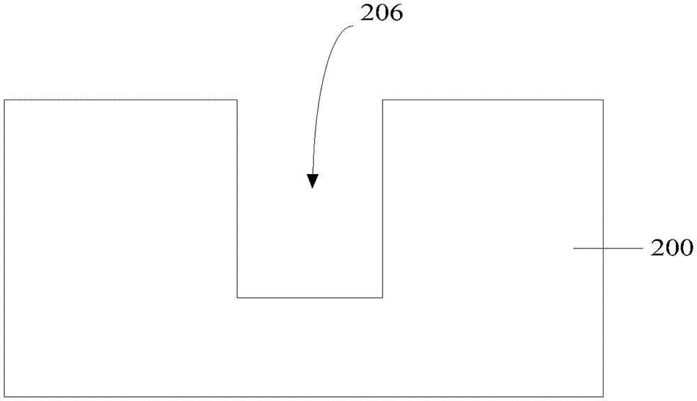
[0030] Please refer to figure 1 , a semiconductor substrate 200 is provided, and a trench 206 is formed in the semiconductor substrate 200 .

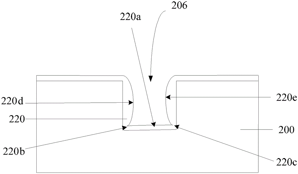
[0031] Please refer to figure 2 , using a thermal oxidation process to form a gate dielectric layer 220 on the bottom and sidewalls of the trench 206, and the gate dielectric layer 220 is silicon oxide.

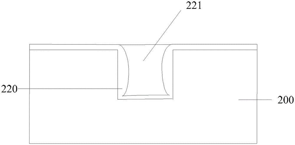
[0032] Please refer to image 3 , forming a trench gate 221 in the trench 206 .

[0033] The inventor discovered and analyzed that, such as figure 2 As shown, after the trench 206 is formed in the substrate, the gate dielectric layer 220 is directly formed on the surface of the trench by a thermal oxi...


PUM


Abstract

A grooved MOS (metal oxide semiconductor) forming method includes the steps: providing a semiconductor substrate; forming a groove in the semiconductor substrate; using the thermal oxidation process to form first gate dielectric layers at the bottom and on the side walls of the groove; using the high-temperature oxidation and deposition process to form second gate dielectric layers on the surfaces of the first gate dielectric layers; and filling a polycrystalline silicon layer in the groove. By the grooved MOS forming method, the problems of poor electric performance and low technical yield of grooved MOSs are solved.

Description

technical field [0001] The invention relates to the field of semiconductor manufacturing, in particular to a method for forming a trench type MOS. Background technique [0002] With the growth of demand for electronic consumer products, the demand for power MOSFETs is increasing, such as disk drives, automotive electronics, and power devices. Trench MOS (TrenchMOS) has lower switching loss and faster switching due to its high integration of devices, low on-resistance, low gate-drain charge density, and large current capacity. speed, is widely used in the field of low voltage power. [0003] For example, more relevant information about trench MOS manufacturing can be found in Chinese Patent Publication No. CN101452857A. However, the electrical performance of the trench MOS formed by the existing process is poor, and the process yield is low. Contents of the invention [0004] The problem to be solved by the present invention is to provide a method for forming a trench ty...

Claims


Application Information

Patent Timeline
Patent Type & Authority Patents(China)
IPC IPC(8): H01L21/336
Inventor 贾璐楼颖颖
Owner SHANGHAI HUAHONG GRACE SEMICON MFG CORP
Why Eureka
Try Eureka