
Adjustable drill hole positioning device and drill hole positioning method for air inlet flange of exhaust manifold

An exhaust manifold and intake flange technology is applied in the field of an adjustable exhaust manifold intake flange drilling positioning device, which can solve the problems of increased processing cost, low qualification rate, high price, etc., and can ensure drilling The effect of hole quality, simple structure and convenient operation

Active Publication Date: 2012-08-29
FEILONG AUTO COMPONENTS CO LTD
View PDF7 Cites 7 Cited by
  • Summary
  • Abstract
  • Description
  • Claims
  • Application Information

AI Technical Summary

Problems solved by technology

This method of processing and positioning is not only inefficient and unable to meet the needs of large-scale industrial production of exhaust manifolds, but also the accuracy of the drilling position is often difficult to guarantee due to the swing of the drill bit, resulting in large errors and low pass rate.
At present, although there are high-efficiency CNC machine tools or machining centers, such processing equipment is not only expensive, but also must be equipped with imported laser scanning devices that cost more than 100,000 yuan, resulting in increased processing costs.

Method used


Image

  • Adjustable drill hole positioning device and drill hole positioning method for air inlet flange of exhaust manifold
  • Adjustable drill hole positioning device and drill hole positioning method for air inlet flange of exhaust manifold
  • Adjustable drill hole positioning device and drill hole positioning method for air inlet flange of exhaust manifold

Examples


Embodiment Construction

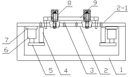
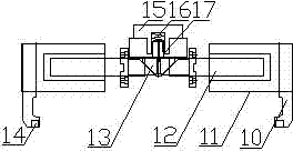
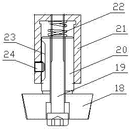
[0020] see figure 1 , figure 2 , image 3 , the adjustable exhaust manifold intake flange drilling positioning device of the present invention has a clamp body 1, and the clamp body 1 is provided with a positioning plane 2-1 at the bottom of the top plate 2 for positioning the reference plane of the exhaust manifold. Z-axis positioning on the exhaust manifold positioning reference plane - the end face of the intake flange. Two sets of single-hole positioning molds 8, a set of double-hole positioning molds 9, and through holes respectively matched with the single-hole positioning molds 8 and the double-hole positioning molds 9 are arranged on the top plate 2, and are provided with drill guides. The drilling template hole 3. At least two sets of workpiece clamping mechanisms are arranged below the positioning drilling template 2 for clamping and fixing the workpiece to be drilled.

[0021] The double-hole positioning mold 9 is used for the X-axis positioning of the exhaust ...


PUM


Abstract

The invention discloses an adjustable drill hole positioning device and a drill hole positioning method for an air inlet flange of an exhaust manifold. The drill hole positioning device is provided with a clamp body; a positioning plane for the positioning of the reference plane of an exhaust manifold is arranged at the bottom of a top plate of the clamp body; a double-hole positioning mold, a single-hole positioning mold and a plurality of through holes matched with the double-hole positioning mold and the single-hole positioning mold are arranged on the top plate; a drill jig hole for guiding a drill is also formed on the top plate; and at least two sets of workpiece clamping mechanisms are arranged below the top plate. As for the drill hole positioning method, two air inlets of the exhaust manifold are used as positioning reference, and the air inlets are positioned in a way of three points. The drill hole positioning device and the drill hole positioning method disclosed by the invention can precisely position the air inlet flange of the exhaust manifold, can reliably ensure the quality of drill holes, and can achieve large-scale production of drill hole machining of air inlet flanges of various exhaust manifolds. The drill hole positioning device has a simple structure, and is low in cost and convenient to operate.

Description

technical field [0001] The invention belongs to the technical field of automobile engine production, in particular to an adjustable exhaust manifold intake flange drilling positioning device and a drilling positioning method. Background technique [0002] The exhaust manifold is an important supporting component of the exhaust system of the automobile engine. Its structure usually has an intake air passage corresponding to the exhaust port of the cylinder of the automobile engine. It is connected to the engine block through connecting bolts; the air outlet is connected to the supercharger through the gas outlet flange, and the supercharger is externally connected to the exhaust manifold. The main functional requirement of the exhaust system is to discharge the exhaust gas in the cylinder to the atmosphere through the exhaust manifold, exhaust manifold, catalytic converter and muffler with as little exhaust resistance and noise as possible. Therefore, in addition to requirin...

Claims


Application Information

Patent Timeline
IPC IPC(8): B23B47/28
Inventor 李振河陈旭孙晶
Owner FEILONG AUTO COMPONENTS CO LTD
Learn More