Difunctional visual light responding catalyst, and preparation method and application thereof

A photocatalyst and catalyst technology, applied in the field of photocatalytic materials, can solve the problems of performance research limitations, poor activity and stability, etc., and achieve the effects of strong visible light response, high activity and stability, and improved utilization

Inactive Publication Date: 2012-09-12
CHINA UNIV OF PETROLEUM (EAST CHINA)
View PDF1 Cites 14 Cited by
  • Summary
  • Abstract
  • Description
  • Claims
  • Application Information

AI Technical Summary

Problems solved by technology

[0006] The invention provides a dual-functional visible light responsive catalyst and its preparation method and application, which can

Method used


Image

  • Difunctional visual light responding catalyst, and preparation method and application thereof
  • Difunctional visual light responding catalyst, and preparation method and application thereof
  • Difunctional visual light responding catalyst, and preparation method and application thereof

Examples


Embodiment 1

[0037] Preparation of nano photocatalyst AgAgCl with strong visible light absorption

[0038]Add 108 mg of polyvinylpyrrolidone and 22 mg of sodium chloride into a 50 mL round-bottomed flask containing 15 mL of glycerol, dissolve in a 60°C oil bath with magnetic stirring, and then quickly inject 1 mL of silver nitrate in glycerine Alcohol solution (52 mg / mL), and increase the magnetic stirring speed to react at 60°C for 1 h; then raise the temperature to 220°C for 10 min. After the reaction was completed, the round-bottomed flask was taken out and naturally cooled to room temperature, centrifuged and washed with deionized water to obtain the AgAgCl visible light catalyst.

[0039] The XPS analysis (X-ray photoelectron spectroscopy) result of the obtained catalyst showed that the mass fraction of silver was 10.2%.

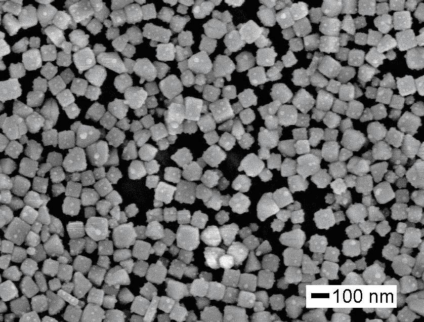
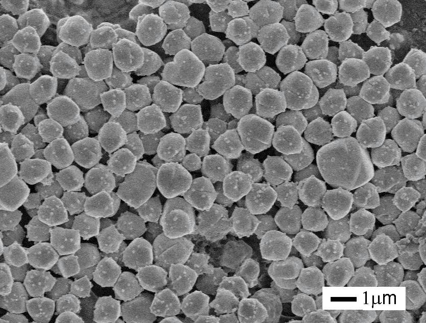
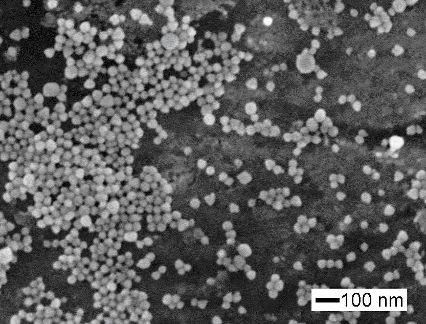
[0040] Picture 1-1 with Figure 1-2 Be respectively the scanning electron microscope (SEM) picture of the AgCl synthesized in embodiment 1 and the visible light ...

Embodiment 2

[0042] Preparation of nano photocatalyst AgAgCl with strong visible light absorption:

[0043] Add 150 mg of polyvinylpyrrolidone and 35 mg of sodium chloride into a 50 mL round-bottomed flask containing 15 mL of glycerol, dissolve with magnetic stirring in an oil bath at 60°C, and then rapidly inject 1 mL of silver nitrate in glycerine Alcohol solution (52 mg / mL), and increase the magnetic stirring speed at 60 ° C for 1 h; then raise the temperature to 220 ° C for 20 min. After the reaction was completed, the round-bottomed flask was taken out and naturally cooled to room temperature, centrifuged and washed with deionized water to obtain the AgAgCl visible light catalyst.

[0044] The result of XPS analysis (X-ray photoelectron spectroscopy) of the obtained catalyst showed that the mass fraction of silver was 15.1%.

Embodiment 3

[0046] Visible light-responsive catalyst AgAgCl with surface plasmon effect for CO reduction 2 performance:

[0047] The obtained AgAgCl catalyst was dispersed in 50 mL of sodium bicarbonate solution (0.1 mol / L), and CO was introduced at a rate of 0.7 L / min. 2 Gas for 10 minutes to remove the air in the reactor, and then under magnetic stirring, use a 300W xenon lamp (with an ultraviolet filter) as a visible light source, and the distance between the light source and the liquid surface is 25 cm, and perform a reduction reaction experiment. After 5 hours of reaction, centrifuge Take out the supernatant, conduct qualitative analysis with gas chromatography-mass spectrometry, and then determine the content of the product with gas chromatography. Then the catalyst was recovered, washed twice with deionized water, and then the cycle reaction experiment was carried out according to the above steps.


PUM


Abstract

The invention provides a difunctional visual light responding catalyst, and a preparation method and application thereof, and can solve the problems that the catalyst has poor activity and stability and the performance study on the catalyst is only limited to the field of pollutant degradation in the prior art. The difunctional visual light responding catalyst has an expression formula of Ag coated AgX, and consists of silver nanoparticles and silver halide, wherein the silver nanoparticles are attached to the surface of the silver halide; silver is 4 to 15 mass percent; and X is Cl or Br. The invention also provides a preparation method and application of the visual light responding catalyst. The prepared catalyst is uniform in particle size and regular in appearance, and the silver nanoparticles are distributed uniformly on the surface of the catalyst; due to a plasma effect of the silver, the catalyst has quick visual light response, can efficiently reduce CO2 and degrade organic dyes to show double functions, and has high activity and stability.

Description

technical field [0001] The invention belongs to the technical field of photocatalytic materials, in particular, relates to a photocatalytic reduction of CO 2 Bifunctional visible light-responsive catalyst for degrading organic pollutants in water and its preparation method and application. Background technique [0002] The rapid development of human society makes atmospheric CO 2 The rising content leads to global climate change, especially a large amount of energy consumption makes environmental problems increasingly prominent, and resources such as oil and natural gas can only last for a few decades. It is imminent to develop clean and efficient environmental governance and new energy technologies. [0003] With the continuous rapid development of the economy and the continuous improvement of people's living standards, my country's energy consumption will maintain a relatively high growth rate for a long period of time, so in CO 2 The fields of emissions and environment...

Claims


Application Information

Patent Timeline
IPC IPC(8): B01J27/10B01J27/08C07C29/159C07C31/04C07C31/08C02F1/30C02F101/30
CPCY02P20/52Y02W10/37
Inventor 安长华王吉壮张锐姜雯王淑涛张钦辉
Owner CHINA UNIV OF PETROLEUM (EAST CHINA)
Why Eureka
Try Eureka