Energy-saving type roller hearth continuous bright normalizing annealing furnace

An energy-saving, annealing furnace technology, applied in the direction of furnaces, furnace components, furnace types, etc., can solve the problems of large energy consumption, deterioration of working conditions for workers, high temperature, etc., to reduce secondary oxidation burning loss, improve the quality of the outer surface, The effect of lowering the temperature of the furnace

Active Publication Date: 2014-05-21
丁永健
View PDF4 Cites 2 Cited by
  • Summary
  • Abstract
  • Description
  • Claims
  • Application Information

AI Technical Summary

Problems solved by technology

Its disadvantages are: the temperature of steel pipes, steel plates and strip steel products directly out of the furnace after annealing or normalizing is as high as 800°C, resulting in a large amount of high-temperature heat energy being released in the atmosphere, resulting in poor working conditions for annealing workers; at the same time, When products such as steel pipes, steel plates, and strip steel are annealed at about 800°C and air-cooled, the iron in the surface layer will chemically react with oxidizing gases (such as oxygen and water vapor) in the air to produce secondary oxidation. After the secondary oxidation of products such as steel plates, steel strips, etc., a thick layer of secondary oxide scale is formed on the surface, which affects the pickling speed of steel pipes, steel plates, and strip steel products, and increases the consumption of sulfuric acid during pickling; if When the finished steel pipe, steel plate and strip steel are annealed, the secondary oxide scale is thicker, which will not only cause the loss of steel, but also reduce the outer surface quality of steel pipe, steel plate and strip steel.
[0003] In addition, most of the high-temperature flue gas in the annealing furnace in the prior art uses an air heat exchanger for waste heat utilization, but the heat exchange effect of the air heat exchanger is poor, and it can only reduce the high-temperature flue gas at about 750°C to 500°C. ℃, there is still a large amount of heat energy in the flue gas that has not been fully utilized, and steel pipes, steel plates, and strip steel products need steam heating in the production process, and it takes a lot of energy to generate steam through coal (gas) boilers. Energy, which is not conducive to enterprises to reduce production costs and wastes national energy resources, but also causes environmental pollution and deteriorates the working conditions of workers

Method used


Image

  • Energy-saving type roller hearth continuous bright normalizing annealing furnace
  • Energy-saving type roller hearth continuous bright normalizing annealing furnace
  • Energy-saving type roller hearth continuous bright normalizing annealing furnace

Examples


Embodiment 1

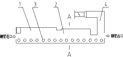
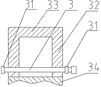
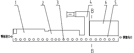
[0027] Such as image 3 , 4 Shown: an energy-saving roller bottom continuous bright positive annealing furnace, including a heating chamber 1, a heat preservation chamber 2, a furnace roller 3, a flue 4 and a waste heat recovery section 5, a heating chamber 1, a heat preservation chamber 2 and a waste heat recovery section 5 Connected in sequence, the furnace roller 3 is installed in the heating chamber 1, the heat preservation chamber 2 and the waste heat recovery section 5 through the bearing housing 31 outside the furnace wall 32, the furnace wall 32 of the waste heat recovery section 5 is above the waste heat recovery boiler 6, and below is the furnace bottom 34, flue 4 is arranged at the tail end of insulation chamber 2.

[0028] In the roller hearth continuous positive annealing furnace, the steel pipe is heated rapidly at a high temperature in the heating chamber 1 and kept warm in the heat preservation chamber 2, and then released from the furnace after being utilized...

Embodiment 2

[0030] Such as Figure 5 Shown: an energy-saving roller bottom continuous bright positive annealing furnace, including a heating chamber 1, a heat preservation chamber 2, a furnace roller 3, a flue 4 and a waste heat recovery section 5, a heating chamber 1, a heat preservation chamber 2 and a waste heat recovery section 5 Connected in sequence, the furnace roller 3 is installed in the heating chamber 1, the heat preservation chamber 2 and the waste heat recovery section 5 through the bearing housing 31 outside the furnace wall 32, the furnace wall 32 of the waste heat recovery section 5 is above the waste heat recovery boiler 6, and below is the furnace bottom 34. There is a flue 4 at the end of the waste heat recovery boiler 6, and there is a smoke pipe inside the waste heat recovery boiler 6.

[0031] In the roller hearth continuous positive annealing furnace, the steel pipe is heated rapidly at a high temperature in the heating chamber 1 and kept warm in the heat preservati...

Embodiment 3

[0033] Such as Figure 6 Shown: an energy-saving roller bottom continuous bright positive annealing furnace, including a heating chamber 1, a heat preservation chamber 2, a furnace roller 3, a flue 4 and a waste heat recovery section 5, a heating chamber 1, a heat preservation chamber 2 and a waste heat recovery section 5 Connected in sequence, the furnace roller 3 is installed in the heating chamber 1, the heat preservation chamber 2 and the waste heat recovery section 5 through the bearing housing 31 outside the furnace wall 32, the furnace wall 32 of the waste heat recovery section 5 is above the waste heat recovery boiler 6, and below is the furnace bottom 34. There is a flue 4 at the inlet end of the heating chamber 1.

[0034] In the roller hearth continuous positive annealing furnace, the steel pipe is heated rapidly at a high temperature in the heating chamber 1 and kept warm in the heat preservation chamber 2, and then released from the furnace after being utilized by...


PUM


Abstract

An energy-saving type roller hearth continuous bright normalizing annealing furnace comprises a heating chamber (1), a heat preservation chamber (2), a furnace roller (3), a flue (4) and a waste heat recovery section (5). A waste heat recovery boiler (6) is arranged on the furnace wall of the waste heat recovery section (5), the flue (4) is arranged at the tail end of the waste heat recovery boiler (6), and a smoke tube is installed in the waste heat recovery boiler (6); a steel tube which is subjected to waste heat utilization by means of the waste heat recovery boiler (6) on waste heat recovery section (5) is discharged from the boiler, and cooled in the air, and the tapping temperature of the steel tube can be controlled around 250 DEG C; and simultaneously, high temperature smoke in the heating chamber (1) and the heat preservation chamber (2) is subjected to waste heat utilization by means of the smoke tube in the waste heat recovery boiler (6) and discharged from the flue (4) at the tail end of the waste heat recovery boiler (6). According to the energy-saving type roller hearth continuous bright normalizing annealing furnace, the waste heat recovery boiler can simultaneously exchange high temperature smoke heat energy and radiant heat energy of the steel tube to produce steam which is used for steel tube production and ordinary life; and besides, the tapping temperature of the steel tube is reduced so that secondary oxidation burning loss is reduced and qualities of outer surfaces of products are improved.

Description

technical field [0001] The invention relates to a heat treatment furnace, in particular to an energy-saving roller bottom continuous bright normal annealing furnace. Background technique [0002] Existing products such as steel pipe, steel plate and strip steel, the structure of the roller bottom continuous normal annealing furnace used in the production process is shown in the attached figure 1 , 2 As shown, it includes a heating chamber 1, a heat preservation chamber 2 and a furnace roller 3, the heating chamber 1 is connected to the heat preservation chamber 2, and the furnace roller 3 is installed in the heating chamber 1 and the heat preservation chamber 2 through the bearing seat 31 outside the furnace wall 32, and the furnace Above the wall 32 is a furnace roof 33, below is a furnace bottom 34, and a flue 4 is arranged at the tail end of the heat preservation chamber 2. In the roller hearth continuous annealing furnace, steel pipes, steel plates, and strip steel pro...

Claims


Application Information

Patent Timeline
Patent Type & Authority Patents(China)
IPC IPC(8): C21D9/56C21D9/08C21D9/00C21D1/26C21D1/28F27D17/00
CPCY02P10/25
Inventor 丁永健丁帅
Owner 丁永健
Why Eureka
Try Eureka