Flywheel energy storage device adopting bearingless switched reluctance motor

A technology for switched reluctance motor and flywheel energy storage, which is applied to the holding device, electromechanical device, and mechanical energy control with magnetic attraction or thrust, which can solve the problem that the cost and efficiency of the flywheel energy storage device are not ideal, and the suspension support and The optimal structure scheme of the transmission motor, the lack of suspension support and the transmission motor structure, etc., achieve the effect of simple structure, shortened axial length, and simple and sturdy structure

Inactive Publication Date: 2012-09-19
JIANGSU UNIV
View PDF5 Cites 35 Cited by
  • Summary
  • Abstract
  • Description
  • Claims
  • Application Information

AI Technical Summary

Problems solved by technology

[0004] However, at present, flywheel energy storage devices mostly use independent transmission and support components, and there are many shortcomings. Because the comprehensive performance requirements of flywheel energy storage devices have not been fully considered, the best structural scheme for suspension support and transmission motor has not been found, and a complete system has not been formed. The structure of the suspension support and the transmission motor makes the cost and efficiency of the flywheel energy storage device far from ideal

Method used


Image

  • Flywheel energy storage device adopting bearingless switched reluctance motor
  • Flywheel energy storage device adopting bearingless switched reluctance motor
  • Flywheel energy storage device adopting bearingless switched reluctance motor

Examples


Embodiment Construction

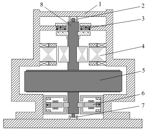
[0025] Such as figure 1 As shown, the present invention includes a housing 1, an upper auxiliary bearing 2, a permanent magnet unloading bearing 3, a magnetic levitation switched reluctance motor 4, a flywheel rotor 5, a hybrid magnetic bearing 6, a lower auxiliary bearing 7 and a flywheel shaft 8. The upper and lower ends of the flywheel rotating shaft 8 are respectively arranged on the upper auxiliary bearing 2 and the lower auxiliary bearing 7, and the upper auxiliary bearing 2 and the lower auxiliary bearing 7 are respectively fixed on the upper and lower ends of the casing 1. The upper end and the lower end of the flywheel rotating shaft 8 are successively fitted with a permanent magnet unloading bearing 3 , a magnetic levitation switched reluctance motor 4 , a flywheel rotor 5 , and a hybrid magnetic bearing 6 . The flywheel rotor 5 is fixedly sleeved on the flywheel rotating shaft 8 . The permanent magnet unloading bearing 3 at the upper end unloads the axial weight of...


PUM


Abstract

The invention discloses a flywheel energy storage device adopting a bearingless switched reluctance motor. A permanent magnetic unloading bearing, a bearingless switched reluctance motor, a flywheel rotor and a mixed magnetic bearing are sequentially sleeved between the upper end and the lower end of a flywheel rotating shaft, wherein the permanent magnetic unloading flywheel carries the axial weight of the flywheel rotating shaft; the mixed magnetic bearing on the lower end overcomes the residual weight and the dynamic load of the flywheel rotating shaft, so that the flywheel rotating shaft is guaranteed to be stably suspended in the axial direction, simultaneously two-degree-of-freedom suspension bearing in the radial direction is provided for the flywheel rotating shaft, and the other two-degree-of-freedom suspension and electric function / power generation function in the axial direction are completed by the bearingless switched reluctance motor; and by adopting the high-speed electromotion / power generation running advantage and the self-suspension function of the bearingless switched reluctance motor, the strong unloading characteristic and the controllable suspension characteristic of the permanent magnetic unloading bearing and the mixed magnetic bearing are reasonably combined, so that the five-degree-of-freedom suspension of a flywheel with low loss and high reliability is realized, the running speed of the flywheel is improved, and the system power consumption and the size are reduced.

Description

technical field [0001] The invention belongs to the technical field of electric energy storage, and in particular relates to a flywheel energy storage device using a magnetic levitation switched reluctance motor, which is especially suitable for the fields of uninterruptible power supply, rail transit, electric power engineering and the like. Background technique [0002] With the rapid development of emerging industries such as new energy, smart grid and electric vehicles, energy storage technology has become an important research topic in the world today. At present, the representative technologies of global energy storage include pumped water storage, compressed air energy storage, battery energy storage, superconducting energy storage, supercapacitor energy storage and flywheel energy storage, among which the flywheel energy storage is to convert electrical energy into the rotational kinetic energy of the flywheel. A physical energy storage technology for storage, which ...

Claims


Application Information

Patent Timeline
Patent Type & Authority Applications(China)
IPC IPC(8): H02K7/02H02N15/00
CPCY02E60/16
Inventor 孙玉坤朱志莹项倩雯张新华周云红
Owner JIANGSU UNIV
Why Eureka
Try Eureka