Solar photovoltaic inverter topology circuit

A solar photovoltaic and topological circuit technology, applied in photovoltaic power generation, instruments, electrical components, etc., can solve the problems of increasing inverter weight, efficiency loss, and high inverter cost, so as to reduce common-mode current interference and improve power conversion Efficiency, the effect of reducing electromagnetic interference

Inactive Publication Date: 2012-09-19
上海神飞能源科技有限公司
View PDF3 Cites 5 Cited by
  • Summary
  • Abstract
  • Description
  • Claims
  • Application Information

AI Technical Summary

Problems solved by technology

like figure 1 As shown, the DC voltage output by the solar panel passes through the inductor L, the fifth IGBT (Insulated Gate Bipolar Transistor, insulated gate bipolar transistor) power switch Q5, the fifth freewheeling diode D5, the clamping diode D, and the capacitor C Form a DC boost circuit; through the first IGBT power switch Q1, the second IGBT power switch Q2, the third IGBT power switch Q3, the fourth IGBT power switch Q4, the first freewheeling diode D1, the second freewheeling diode D2, The full-bridge inverter circuit composed of the third freewheeling diode D3 and the fourth freewheeling diode D4 inverts, and then realizes the output of alternating current through isolation by the power frequency transformer, and the output alternating current passes through the first choke inductor L1 and the first capacitor C1 The grid-connected output is filtered by the composed low-pass filter; this grid-connected topology has the following disadvantages: 1. Due to the use of power frequency isolation transformers, the cost of the inverter is relatively high
Second, the power frequency isolation transformer reduces the conversion efficiency of the inverter
3. Due to the use of power frequency isolation transformers, the weight of the inverter is increased
[0004] like figure 2 As shown, the DC voltage output by the solar panel passes through the DC boost circuit composed of the inductor L, the fifth IGBT power switch Q5, the fifth freewheeling diode D5, the clamping diode D, and the capacitor C; Q1, second IGBT power switch Q2, third IGBT power switch Q3, fourth IGBT power switch Q4, first freewheeling diode D1, second freewheeling diode D2, third freewheeling diode D3, fourth freewheeling diode D4 The full-bridge inverter circuit constitutes inversion; then through the first choke inductance L1, the second choke inductance L2, the first capacitor C1, the conductance switch is connected to the high-frequency transformer T1 to output the alternating current; and then through the sixth embedding Diode D6, the seventh clamping diode D7, the eighth clamping diode D8, the ninth clamping diode D9, the tenth clamping diode D10, the eleventh clamping diode D11, the twelfth clamping diode D12, the tenth clamping diode The power frequency converter composed of the three clamping diodes D13, the sixth IBGB power switch Q6, the seventh IBGB power switch Q7, the eighth IBGB power switch Q8, and the ninth IBGB power switch Q9 realizes the AC output; finally, through the third inductor L3 and The grid-connected output is filtered by the low-pass filter formed by the second capacitor C2; this grid-connected topology has the following disadvantages: 1. Due to the use of high-frequency isolation transformers, there are also problems such as efficiency loss and weight.
2. Due to the use of power frequency converters, the cost of photovoltaic inverters is increased

Method used


Image

  • Solar photovoltaic inverter topology circuit
  • Solar photovoltaic inverter topology circuit
  • Solar photovoltaic inverter topology circuit

Examples


Embodiment Construction

[0015] A preferred embodiment is given below to illustrate the present invention more clearly and completely in conjunction with the accompanying drawings.

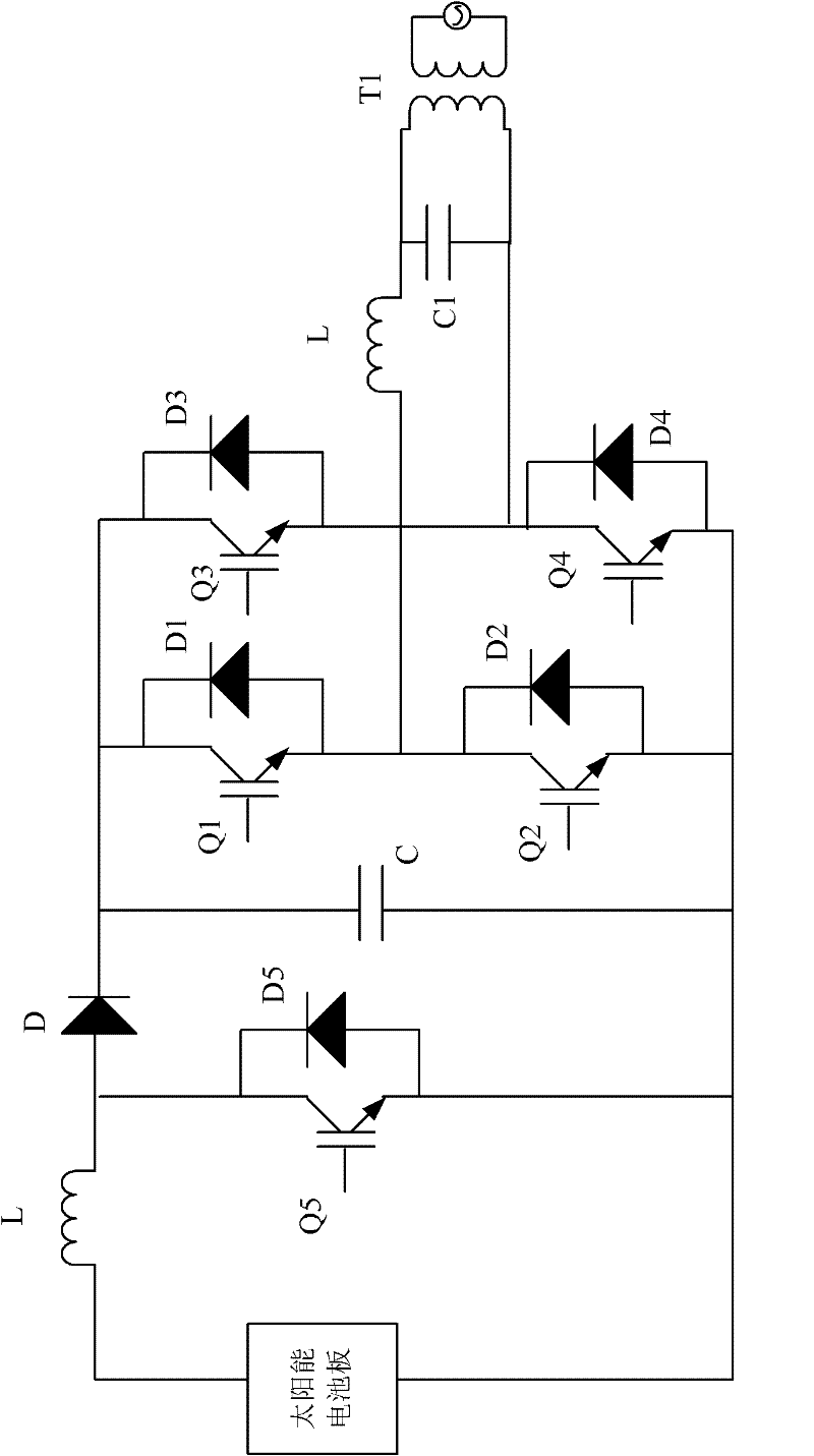
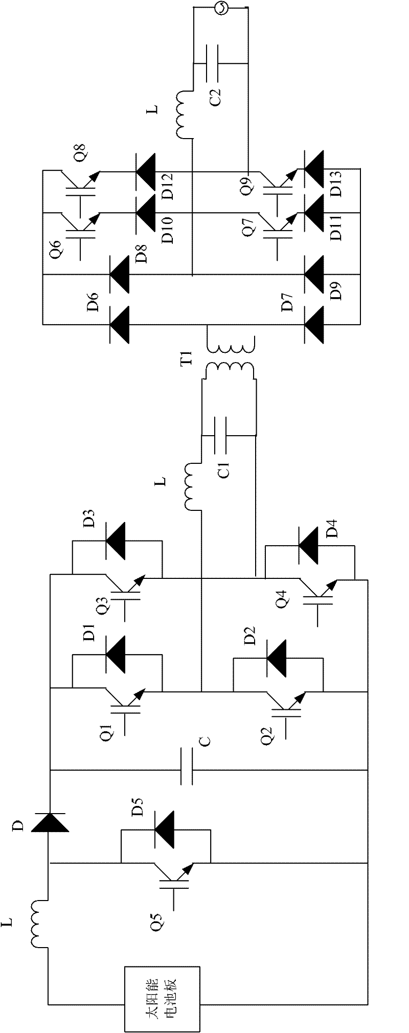
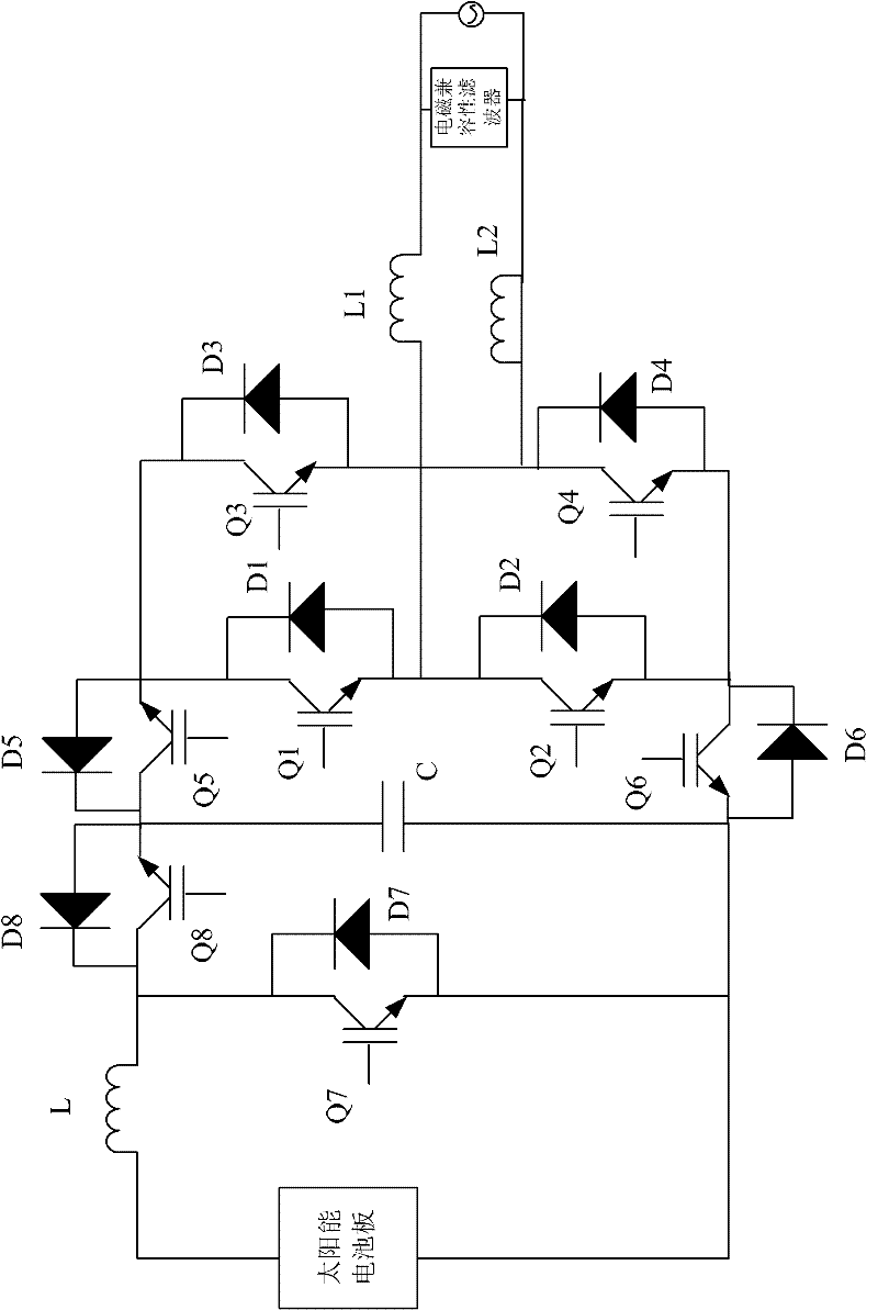
[0016] Such as image 3 with Figure 4 As shown, the topological circuit of the solar photovoltaic inverter of the present invention includes a DC boost circuit, a DC conversion AC inverter circuit and an electromagnetic compatibility filter, the DC boost circuit is connected with the solar panel, the DC conversion AC inverter circuit, and the DC conversion The AC inverter circuit is connected to the electromagnetic compatibility filter, and the electromagnetic compatibility filter is connected to the grid. The specific structure of the present invention is as follows: the solar panel is connected in series with the inductor L, and the solar panel is connected in parallel with the eighth IGBT power switch Q8, the eighth freewheeling diode D8, the seventh IGBT power switch Q7, the seventh freewheeling diode D7 and the capacit...


PUM


Abstract

The invention discloses a solar photovoltaic inverter topology circuit, which comprises a direct current voltage boosting circuit, a direct current-to-alternating current inverter circuit and an electromagnetic compatible filter, wherein the direct current voltage boosting circuit is connected with a solar panel and the direct current-to-alternating current inverter circuit, the direct current-to-alternating current inverter circuit is connected with the electromagnetic compatible filter, and the electromagnetic compatible filter is connected with an electric network. The output voltage of a solar battery firstly passes through the direct current voltage boosting circuit of a solar maximum power point tracker and then passes through the direct current-to-alternating current inverter circuit to obtain alternating current power to be directly subjected to networking, so the inverting process loss of an inverter is reduced.

Description

Technical field [0001] The invention relates to an inverter, in particular to a solar photovoltaic inverter topology circuit. Background technique [0002] With the increasingly serious energy shortage and environmental pollution problems in the 21st century, the development and application of renewable clean energy has attracted more and more attention from governments around the world; since the 1980s, solar photovoltaic power generation technology has gained rapid The development of solar photovoltaic grid-connected power generation has become one of the main ways to use solar energy; to carry out research on solar photovoltaic grid-connected inverter systems and high-performance distributed power generation systems, which is useful for exploring the broad photovoltaic power generation market and mastering the field of power electronics The advanced technology, alleviation of energy and environmental problems, are of far-reaching significance. [0003] At present, there are two...

Claims


Application Information

Patent Timeline
Patent Type & Authority Applications(China)
IPC IPC(8): H02M7/48H02M3/155H02M7/5387H02M1/44
CPCY02E10/56
Inventor 沈永兵徐进黄景春
Owner 上海神飞能源科技有限公司
Why Eureka
Try Eureka