Method for deeply processing metal material by aid of laser

A metal material and laser processing technology, applied in metal processing equipment, laser welding equipment, manufacturing tools, etc., to achieve high energy density, small spot, and good beam quality

Active Publication Date: 2012-09-26
江苏华工激光科技有限公司
View PDF9 Cites 6 Cited by
  • Summary
  • Abstract
  • Description
  • Claims
  • Application Information

AI Technical Summary

Problems solved by technology

It is a method of processing metal materials by using the characteristics of high power density and high peak power of laser combined with the characteristics of coatings to solve the problems that cannot be solved by traditional processing methods; it can cooperate with traditional processing methods, first use milling to process the approximate outline, and then Use laser to process the sharp corners that are not processed by milling machine, or directly use laser processing to meet the requirements of different depth, effect and efficiency

Method used


Image

  • Method for deeply processing metal material by aid of laser
  • Method for deeply processing metal material by aid of laser
  • Method for deeply processing metal material by aid of laser

Examples


Embodiment 1

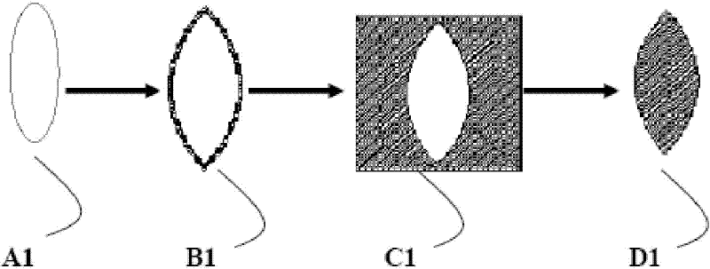
[0044] Take processing a leaf pattern as an example, such as image 3 As shown, on a 1mm thick 6061 aluminum alloy plate (commercially available), process a leaf-shaped pattern (figure size is 15mmx40mm), and the processing depth is 0.3mm; the specific steps are as follows:

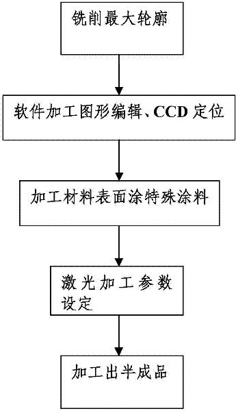
[0045] Step A1: first use a milling machine to process the largest outline of the leaf;

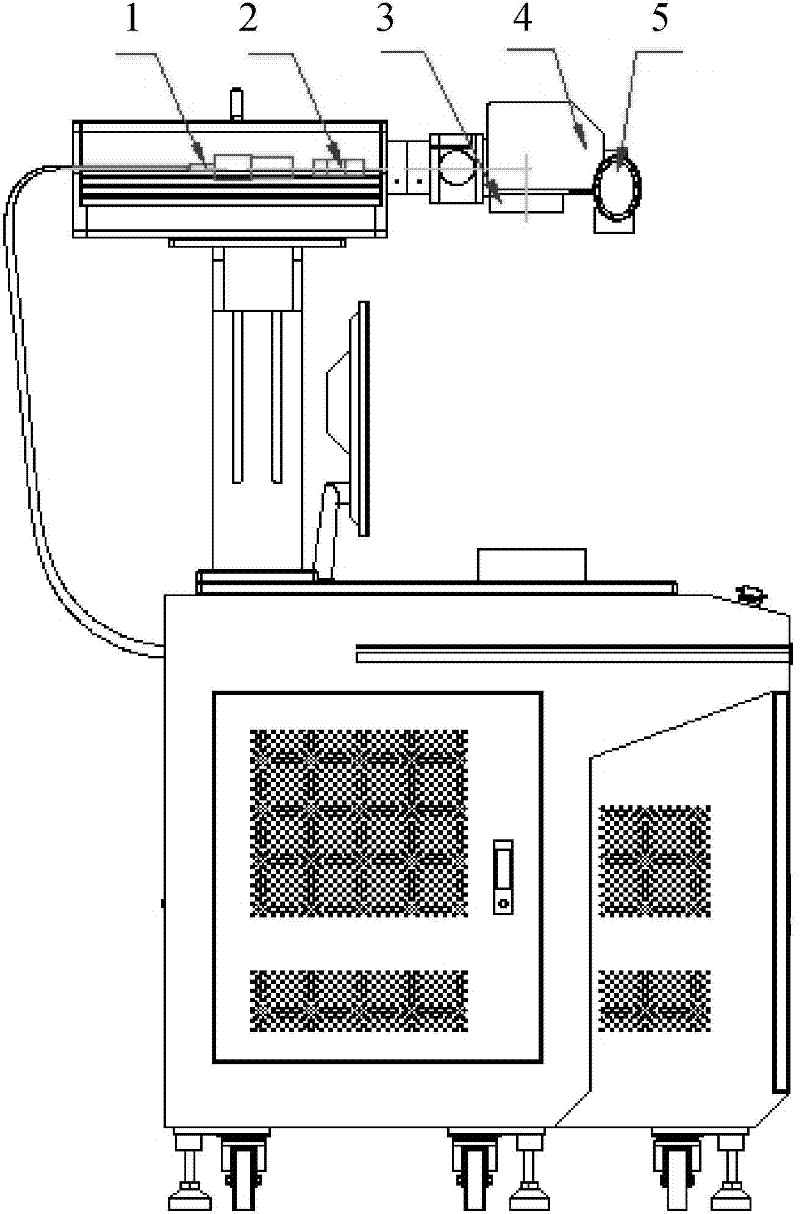
[0046]Step B1: Edit the processing part that the engraving and milling machine failed to complete in step A1 in the laser engraving software, and use the CCD positioning system (to identify the position of the graphics that need to be processed, to ensure the relative position of the laser processing graphics and the CNC machining outline) to determine the processing position, and choose a fiber laser with a power of 20W (to provide light source and process energy source), F=160mm focusing lens (to focus the spot formed by the laser after passing through the beam expander, and improve the power density of the spot), ...

Embodiment 2

[0050] Take processing a five-pointed star pattern as an example, such as Figure 4 As shown, on a T magnesium-aluminum alloy plate (brand T934, commercially available) with a thickness of 1mm, process a five-pointed star pattern (figure size is 40mmx40mm), and the processing depth is 0.4mm; the specific steps are as follows:

[0051] Step A2: First use a milling machine to process the largest outline of the five-pointed star;

[0052] Step B2: Edit the processing part that the engraving and milling machine failed to complete in step A2 in the laser engraving software, and use the CCD positioning system (to identify the position of the graphics that need to be processed, to ensure the relative position of the laser processing graphics and the CNC machining contour) to determine the processing position, and choose a fiber laser with a power of 20W (to provide light source and process energy source), F=160mm focusing lens (to focus the spot formed by the laser after passing thro...


PUM


Abstract

The invention relates to a method for deeply processing a metal material by the aid of laser. A processed area is determined by a CCD (charge coupled device) positioning system, a layer of special material is coated on the surface of the metal material to eliminate influences of processing heat in advance, and after passing through a beam expander with the proper magnification and a lens with the proper focal length, pulse light transmitted by a laser device is focused on the surface of the metal material and matches with selected laser processing parameters so that deep processing is carried out. Compared with other processing modes (such as linear cutting), the method is higher in flexibility, and can be used for processing various patterns which cannot be processed by linear cutting or chemical etching. When products (such as blind holes) do not need to be perforated, laser can be directly used for processing shapes with smaller sharp corners as compared with milling and cutting processing owing to the characteristics of small light spot and high energy density of ht laser. Besides, the surface of the processed material is coated with aqueous compound coating before the material is processed, so that edges processed by the laser are smoother.

Description

technical field [0001] The invention relates to a method for deep processing of metal materials by using laser, and belongs to the technical field of metal materials. Background technique [0002] At present, in industrial applications, it is common to use metal materials as equipment, product casings, and internal mechanical components. In the processing process, it is often necessary to process a certain depth on the stainless steel and aluminum alloy shells. Through deep processing, it enters the positioning and inlay of the next process to meet the shape design requirements of the product and play a role in beautifying the product layout. Nowadays, turning, milling, CNC machining or chemical etching are commonly used for deep processing. However, the above method cannot solve the problems of sharp corners, efficiency, relatively large equipment consumables, and processing complexity of received materials. For example, during CNC machining, due to the limitation of the...

Claims


Application Information

Patent Timeline
Patent Type & Authority Applications(China)
IPC IPC(8): B23K26/36B23K26/42B23K26/60
Inventor 刘勇孙威余坤闵大勇卢飞星
Owner 江苏华工激光科技有限公司
Why Eureka
Try Eureka