

Fuel-cell catalyst slurry and preparation method thereof
A catalyst slurry, fuel cell technology, applied in battery electrodes, circuits, electrical components, etc., can solve problems such as limited stability and complex preparation procedures, and achieve the effects of good uniformity, easy operation and improved efficiency
- Summary
- Abstract
- Description
- Claims
- Application Information
AI Technical Summary
Problems solved by technology
Method used
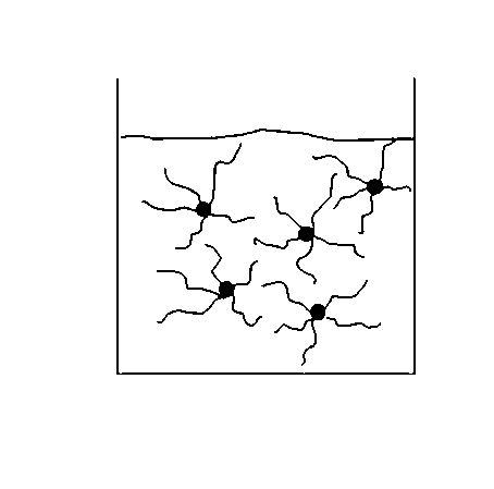
Image

Examples
Embodiment 1
[0031] Take 1 g of polyvinylpyrrolidone (PVP) and 10 g of water, add them into a beaker, stir magnetically at room temperature for 0.5 h, and mix evenly to obtain a solution of a polymer dispersant.
[0032] Take 10ml of ethanol and 10ml of deionized water, add them into a beaker, stir magnetically at room temperature for 0.5h, and mix well to obtain a 1:1 ethanol / water mixed solution.
[0033] Take 0.1g of Pt black produced by Johnson Matthy (Jonhson Matthy), add 0.11g of perfluorosulfonic acid (10%Nafion, Dupont), stir magnetically for 5min, and add 2ml of the above-mentioned 1:1 ethanol / water mixed solution , magnetically stirred for 30 min. Finally, 0.03 g of the above-mentioned polymer dispersant solution was added while stirring; the stirring was continued for 1.5 h until the mixture was evenly mixed to obtain a catalyst slurry of the present invention.
Embodiment 2
[0035] Take 1 g of sodium carboxymethyl cellulose (CMC) and 10 g of water, add them to a beaker, stir magnetically at room temperature for 0.5 h, and mix well to obtain a solution of polymer dispersant.
[0036] Take 10ml of ethylene glycol and 10ml of deionized water, add them into a beaker, stir magnetically at room temperature for 0.5h, and mix well to obtain a 1:1 ethanol / water mixed solution.
[0037] Take 0.1g platinum ruthenium-black (Pt-Ru Black) produced by Johnson Matthy (Jonhson Matthy), add 0.08g Nafion (10%Nafion, Dupont), stir magnetically for 5min, add the above-mentioned 1:1 ethanol and Mixed solution of water 1.5ml, magnetically stirred for 30min. Finally, 0.05 g of the above-mentioned high molecular polymer dispersant solution was added while stirring, and the stirring was continued for 2 hours until the mixture was evenly mixed to obtain a catalyst slurry of the present invention.
Embodiment 3
[0039] Take 1.2 g of polyvinyl alcohol (PVA) and 10 g of water, add them into a beaker, stir magnetically at room temperature for 0.5 h, and mix well to obtain a solution of a polymer dispersant.
[0040] Take 10ml of propanol and 10ml of deionized water, put them into a beaker, stir magnetically at room temperature for 0.5h, and mix well to get a 1:1 ethanol / water mixed solution.
[0041] Take 0.1g Pt-Black (Pt-Black) produced by Johnson Matthey, add 0.15g Nafion, stir magnetically for 5min, add 2.5ml of the above 1:1 mixed solution of ethanol and water, stir magnetically for 30min. Finally, 0.02 g of the above-mentioned polymer dispersant solution was added while stirring, and the stirring was continued for 5 hours until the mixture was evenly mixed to obtain a catalyst slurry of the present invention.
PUM
 Abstract
Description
Claims
Application Information