Treatment method for improving oxidation resistance of thermal barrier coating (TBC) bonding layer

A technology of thermal barrier coating and treatment method, which is applied in the direction of coating, metal material coating technology, fusion spraying, etc., and can solve the problem of uneven growth of thermally grown oxide layer, reduction of oxidation resistance of coating, and bonding layer surface Large roughness and other problems, to achieve the effect of uniform thermal growth oxide layer, high energy utilization rate, and improve high temperature service performance

Inactive Publication Date: 2012-10-10
DALIAN UNIV OF TECH
View PDF3 Cites 23 Cited by
  • Summary
  • Abstract
  • Description
  • Claims
  • Application Information

AI Technical Summary

Problems solved by technology

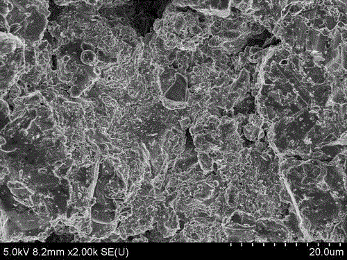
[0006] The second is that the surface roughness of the bonding layer prepared by the plasma spraying method is relatively large, which makes the interface between the bonding

Method used


Image

  • Treatment method for improving oxidation resistance of thermal barrier coating (TBC) bonding layer
  • Treatment method for improving oxidation resistance of thermal barrier coating (TBC) bonding layer
  • Treatment method for improving oxidation resistance of thermal barrier coating (TBC) bonding layer

Examples


Example Embodiment

[0025] Example 1:

[0026] Combining the specific experimental process, the implementation scheme of high-current pulsed electron beam irradiation to improve the high-temperature oxidation resistance of the thermal barrier coating bonding layer is described in detail. Taking the same pulse width and different energy density as an example, the specific steps are as follows:

[0027] The first step is the preparation of the thermal barrier coating bonding layer (MCrAlY)

[0028] After the high-temperature alloy substrate (or engine blades and other components) is pre-grinded, polished, and cleaned, a bonding layer is deposited on the high-temperature alloy substrate by low-pressure plasma spraying (LPPS). The coating material of the bonding layer is MCrAlY;

[0029] The second step is to fix the sample with the thermal barrier coating bonding layer sprayed on the sample table and vacuum

[0030] Fix the thermal barrier coating bonding layer sample prepared by the plasma spraying method on...

Example Embodiment

[0039] Example 2:

[0040] Combining the specific experimental process, the implementation scheme of high-current pulsed electron beam irradiation to improve the high-temperature oxidation resistance of the thermal barrier coating bonding layer is described in detail. Taking the same energy density and different pulse widths as an example, the specific steps are as follows:

[0041] The first step is the preparation of the thermal barrier coating bonding layer (MCrAlY)

[0042] After the superalloy substrate (or engine blades and other components) is pre-grinded, polished, and cleaned, a bonding layer is deposited on the superalloy substrate by low-pressure plasma spraying (LPPS). The coating material of the bonding layer is MCrAlY;

[0043] The second step is to fix the sample with the thermal barrier coating bonding layer deposited on the sample stage and vacuum

[0044] Fix the thermal barrier coating bonding layer sample prepared by the plasma spraying method on the sample stage of ...


PUM


Abstract

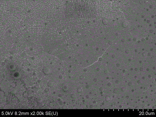
The invention relates to a treatment method for improving the oxidation resistance of a thermal barrier coating (TBC) bonding layer, and belongs to the technical field of surface treatment and modification of the TBC bonding layer. In the material surface treatment and modification processes, the surface roughness of the TBC bonding layer (MCrAlY) prepared by a plasma spraying method is reduced through high current pulsed electron beam irradiation, and the pores and holes of a coating are reduced, so that the high-temperature oxidation resistance of the TBC bonding layer is improved. Technical conditions are that vacuum degree is 3.5*10<-2>Pa, voltage is 15kV, frequency is 1Hz, pulse width is 50 to 200mu s, energy density is 8 to 18J/cm<2>, and pulse times is 10 to 20. The method has the advantages that the surface roughness of the TBC bonding layer (MCrAlY) prepared by the plasma spraying method is reduced through high current pulsed electron beam irradiation, the pores and holes of the coating are reduced, and penetrated microcracks are avoided, so that the high-temperature oxidation resistance of the TBC bonding layer is effectively improved.

Description

technical field [0001] The invention relates to a treatment method for improving the oxidation resistance of the bonding layer of a thermal barrier coating, that is, the high-current pulsed electron beam irradiation realizes the remelting of the surface of the bonding layer of the thermal barrier coating prepared by the plasma spraying method, and the coating surface is smooth , the loose pores disappear and the roughness is reduced, thereby improving the oxidation resistance of the bonding layer of the thermal barrier coating, belonging to the technical field of surface treatment and modification of the bonding layer of the thermal barrier coating. Background technique [0002] With the development of aerospace technology, the service temperature of hot end parts such as engine turbine blades is getting higher and higher, which puts forward higher requirements for the high temperature resistance of the superalloy used to prepare the blades. One of the methods to solve the pr...

Claims


Application Information

Patent Timeline
IPC IPC(8): C23C4/18C23C24/10
Inventor 梅显秀刘越马腾才
Owner DALIAN UNIV OF TECH
Why Eureka
Try Eureka