Dynamic rotary kiln supporting roller shaft deflection variation and cylinder bending measuring method and instrument

A measuring method and technology of supporting roller shaft, applied in the direction of instruments, measuring devices, etc., can solve the problems of easy hidden submersion, large measurement error of deflection change, etc., and achieve the effect of preventing sudden breakage

Active Publication Date: 2012-10-17
WUHAN UNIV OF TECH
View PDF3 Cites 6 Cited by
  • Summary
  • Abstract
  • Description
  • Claims
  • Application Information

AI Technical Summary

Problems solved by technology

However, due to the shape factors of the uneven contour and out-of-roundness on the surface of the supporting roller, they cause the deflection value of the supporting roller to be 1-4mm, and the deflection of the supporting roller shaft is only 0.1-0.3mm, which is easy to hide and submerge in the uneven contour being deformed
Therefore, the disadvantage of this method is that it is difficult to distinguish the small value of the real shaft deflection change from the large value of the deflection caused by factors such as uneven contours on the surface of the supporting wheel and vibration with only one displacement sensor, resulting in a large measurement error of the deflection change

Method used


Image

  • Dynamic rotary kiln supporting roller shaft deflection variation and cylinder bending measuring method and instrument
  • Dynamic rotary kiln supporting roller shaft deflection variation and cylinder bending measuring method and instrument
  • Dynamic rotary kiln supporting roller shaft deflection variation and cylinder bending measuring method and instrument

Examples


Embodiment Construction

[0020] The present invention is described in detail below with reference to accompanying drawing and specific embodiment:

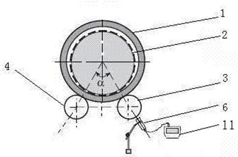
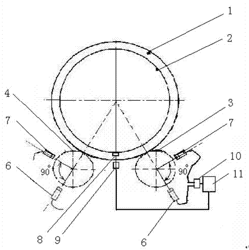
[0021] figure 1 It has been introduced in the existing background technology section, and is omitted here. like figure 2 Shown, the inventive method concrete method is as follows:

[0022] At a fixed position below the high end of the cylinder, use a trigger 8 to adsorb on the cylinder 2 to determine the busbar for starting and ending the measurement, use a position sensor 9 to measure the rotation period of the cylinder 2, and use the equal cycle time to determine Determine the rotation orientation of the barrel.

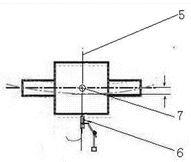
[0023] (1) if image 3 As shown, at the same middle section 5 of the left supporting wheel 4 of the same block, two displacement sensors perpendicular to each other are installed in alignment with the center of the left supporting wheel. The first displacement sensor 6 on the extension line of the connection between the left supporti...


PUM


Abstract

The invention relates to a dynamic rotary kiln supporting roller shaft deflection variation and cylinder bending azimuth measuring method and instrument. The method comprises the following steps: determining a cylinder rotation period and a measurement bus by a position sensor; mounting two orthogonal displacement sensors to carry out measurement, and processing the two set of data to obtain the supporting roller shaft deflection variation value, wherein the two displacement sensors are mounted on the same middle section of the left and right supporting rollers of the same shift, and aligned with the centers of the supporting rollers; and correlating the cylinder rotation azimuth with the deflection variation value of the left and right supporting roller shafts of the same group, carrying out comparative analysis to obtain a supporting roller loading and stressing condition curve, and determining the cylinder bending azimuth; and sequentially repeating the operation above at the roller belt of each shift, measuring the deflection variation data of the left and right supporting rollers of each shift, and determining the supporting roller adjustment direction and data by referring to the supporting roller space geometric position parameters and dynamic rotary kiln central line measurement results. The measuring apparatus comprises two displacement sensors, a position sensor, a multichannel data acquisition card and a microcomputer. The measurement accuracy of the method for measuring the supporting roller shaft deflection is 0.001mm; and the measurement accuracy for measuring the cylinder bending is 0.5mm.

Description

technical field [0001] The invention relates to a method for measuring the mechanical deformation of a rotary kiln supporting wheel shaft and a cylinder body, in particular to a method and an instrument for measuring the deflection variation of a dynamic rotary kiln supporting wheel shaft and the cylinder body bending. Background technique [0002] Rotary kiln is an important firing equipment for industries such as cement, non-ferrous and ferrous metallurgy, chemical industry, and refractory materials. The rotary kiln is generally operated continuously by multi-point support of three-speed (and above) supporting wheels. The ideal axis of the rotary kiln is a straight line, and the supporting wheels support the kiln body evenly. In the long-term operation, due to the uneven settlement of the kiln base pier, the deviation of the position of the supporting roller, and the bending and deformation of the kiln shell at the supporting roller, the force on each supporting roller ...

Claims


Application Information

Patent Timeline
Patent Type & Authority Applications(China)
IPC IPC(8): G01B21/32G01B21/20
Inventor 张云其他发明人请求不公开姓名
Owner WUHAN UNIV OF TECH
Why Eureka
Try Eureka