Laminated coil component

A technology of laminated coils and devices, applied in coil manufacturing, transformer/inductor parts, inductors, etc., can solve the problems of internal conductor layer thickness, internal conductor layer disconnection, external electrode peeling, etc., to achieve less characteristic deviation, Prevention of disconnection and high impedance value

Active Publication Date: 2012-10-17
MURATA MFG CO LTD
View PDF5 Cites 1 Cited by
  • Summary
  • Abstract
  • Description
  • Claims
  • Application Information

AI Technical Summary

Problems solved by technology

[0003] Furthermore, the laminated coil device obtained by simultaneously firing ferrite and internal conductor has the following problem: the internal stress caused by the difference in thermal expansion coefficient between the ferrite layer and the internal conductor layer will cause the ferrite magnetic The characteristics drop, causing the drop or deviation of the impedance value of the laminated coil device
[0006] Therefore, there is a problem that it is difficult to obtain a product with low DC resistance
In particular, if it is a small product such as a product with a size of 1.0mm x 0.5mm x 0.5mm or a product with a size of 0.6mm x 0.3mm x 0.3mm, there is a problem that it is difficult to make the ferrite layer thinner. Since the internal conductor layer and the void are provided between the body layers and the internal conductor layer is formed thick, not only the DC resistance cannot be reduced, but also the internal conductor layer is likely to be disconnected due to impact, etc., and sufficient reliability cannot be ensured.
[0008] However, in the case of utilizing this method, since a highly corrosive solution such as an aqueous solution containing halides, an aqueous solution containing hydrohalic acid, an aqueous solution containing sulfuric acid, an aqueous solution containing oxalic acid, or an aqueous solution containing nitric acid is used, not only It will corrode the interface with the internal electrode, and it will also corrode the interface with the external electrode, which will reduce the bonding force of the external electrode and may cause problems such as peeling of the external electrode.

Method used


Image

  • Laminated coil component
  • Laminated coil component
  • Laminated coil component

Examples


Embodiment 1

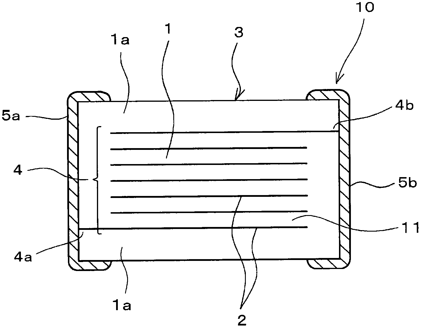
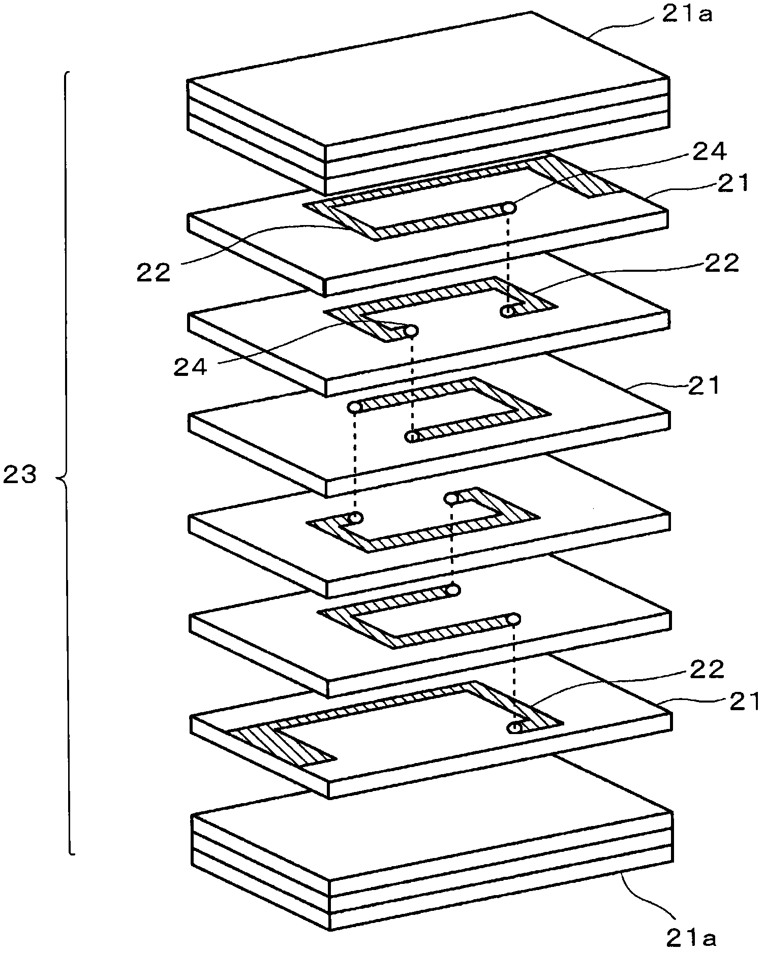
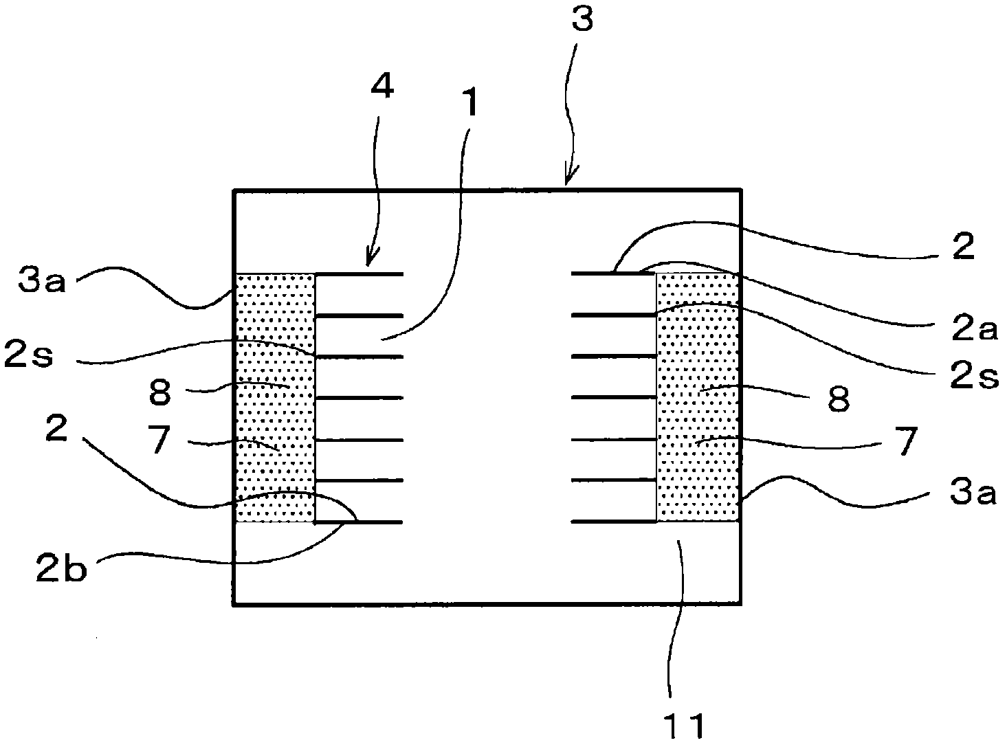
[0070] figure 1 It is a front cross-sectional view showing the structure of a laminated coil device (in this embodiment 1, a laminated impedance element) according to an embodiment (Example 1) of the present invention, figure 2 is an exploded perspective view showing its manufacturing method, image 3 yes figure 1 Side cross-sectional view of the structure of a laminated coil device.

[0071] like Figure 1 ~ Figure 3 As shown, this laminated coil device 10 is manufactured through the process of firing a laminate obtained by laminating a ferrite layer 1 and a coil-forming internal conductor 2 mainly composed of Ag. The element 3 is provided with a helical coil 4 inside.

[0072] In addition, a pair of external electrodes 5 a , 5 b are arranged at both end portions of the ferrite element 3 so as to conduct with both end portions 4 a , 4 b of the helical coil 4 .

[0073] In addition, in this laminated coil device 10, there is no gap at the interface between the internal c...

Embodiment 2

[0154] In addition to using a 0.2 mol / L aqueous solution of gluconolactone (manufactured by Nacalai Tesque), to replace the complexing agent solution (citric acid-hydrate 0.2 mol / L aqueous solution), to immerse the laminated impedance element (sample) in the gluconolactone 0.2mol / L aqueous solution for 3, 6, 12, 24 hours, except for stress relaxation treatment, all use the above-mentioned implementation In the same manner as in Example 1, a laminated impedance element (sample) was produced.

[0155] In addition, in this example, although 0.2 mol / L aqueous solution of gluconolactone was used as the complexing agent solution, the concentration is not limited thereto, and it can be set to an appropriate concentration in consideration of various conditions. In addition, it is not limited to water solubility, and a solution obtained by dissolving a complexing agent in a solvent other than water can also be used.

[0156] Next, for the manufactured multilayer impedance element, the C...

Embodiment 3

[0164] In order to investigate the effect of the pore area ratio of the side gap on the stress relaxation effect, the firing temperature of (6) in Example 1 was changed in the range of 840-900°C, so that the pore area ratio of the side gap was produced 26-3% laminated impedance element (sample), and use citric acid-hydrate 0.2mol / L aqueous solution as a complexing agent solution for stress relaxation treatment. In addition, in other respects, the same method and conditions as in Example 1 above were set.

[0165] Next, the Cu segregation rate, impedance (|Z| at 100 MHz), flexural strength, and pore area ratio of the side gap were examined in the same manner as in Example 1 above.

[0166] The results are shown in Table 4.

[0167] [Table 4]

[0168]

[0169] As shown in Table 4, it has been confirmed that when the sample is sintered at 855-885°C, the pore area ratio of the side gap is in the range of 6-20%, and the Cu segregation rate is 5% or less (1.5-1.8% ), it is pos...


PUM

PropertyMeasurementUnit
sizeaaaaaaaaaa
sizeaaaaaaaaaa
Area ratioaaaaaaaaaa

Abstract

Provided is a highly reliable laminated coil component which does not require an opening to be formed between a ferrite layer and an internal conducting layer as conventionally, and enables alleviation of the internal stress between the ferrite layer and internal conducting layer caused by the difference between the firing shrinkage behavior and thermal expansion coefficient. A process is prepared for dissociating the boundary between the internal conductor (2) and the surrounding ferrite (11). This is done by enabling a complexing agent solution to reach a boundary between an internal conductor and ferrite (11) surrounding it by passing it from a side surface (3a) of a ferrite element (3) containing a spiral-shaped coil (4) and then through a side gap part (8). As the complexing agent solution, a solution is used that includes at least one substance selected from a group comprising aminocarboxylic acid and its salt, oxycarboxylic acid and its salt, amine, phosphoric acid and its salt and a lactone compound.

Description

technical field [0001] The present invention relates to a laminated coil device having a ceramic laminate formed by laminating a ferrite layer and an internal conductor for coil formation mainly composed of Ag, which is formed by firing a ferrite The interior of the oxygen layer element is provided with a helical coil structure. Background technique [0002] In recent years, the demand for miniaturization of electronic devices has been increasing, and the mainstream of coil devices has gradually shifted to multilayer coil devices. [0003] Furthermore, the laminated coil device obtained by simultaneously firing ferrite and internal conductor has the following problem: the internal stress caused by the difference in thermal expansion coefficient between the ferrite layer and the internal conductor layer will cause the ferrite magnetic The characteristic drops, causing a drop or variation in the impedance value of the laminated coil device. [0004] Therefore, in order to el...

Claims


Application Information

Patent Timeline
Patent Type & Authority Applications(China)
IPC IPC(8): H01F17/00H01F41/04
CPCH01F2027/2809H01F17/04H01F27/2804H01F41/046H01F17/0013H01F41/04H01F17/00
Inventor 小田原充元木章博大野晃弘
Owner MURATA MFG CO LTD
Why Eureka
Try Eureka