Raman optical fiber amplifier and detection method of loss of transmission optical fiber connector of Raman optical fiber amplifier

A Raman optical fiber and joint loss technology, applied in lasers, laser components, optics, etc., can solve the problems of easy pollution of the output end face of the amplifier, large insertion loss of the connection between the amplifier and the transmission fiber, and insufficient environmental cleanliness, etc., to achieve Optimize system application, precisely control gain size and gain slope, and improve performance

Active Publication Date: 2012-10-24
GUANGXUN SCI & TECH WUHAN
View PDF3 Cites 26 Cited by
  • Summary
  • Abstract
  • Description
  • Claims
  • Application Information

AI Technical Summary

Problems solved by technology

[0003] In the engineering application of Raman fiber amplifier, because the environment is not clean enough, the output end face of the amplifier is easily polluted, which leads to the increase of the insertion loss of the connection between the amplifier and the transmission fiber, which affects the application of the Raman fiber amplifier

Method used


Image

  • Raman optical fiber amplifier and detection method of loss of transmission optical fiber connector of Raman optical fiber amplifier
  • Raman optical fiber amplifier and detection method of loss of transmission optical fiber connector of Raman optical fiber amplifier
  • Raman optical fiber amplifier and detection method of loss of transmission optical fiber connector of Raman optical fiber amplifier

Examples


Embodiment Construction

[0038] The Raman fiber amplifier of the present invention and the method for detecting the loss of the transmission fiber joint are described in detail below in combination with the embodiments and the accompanying drawings.

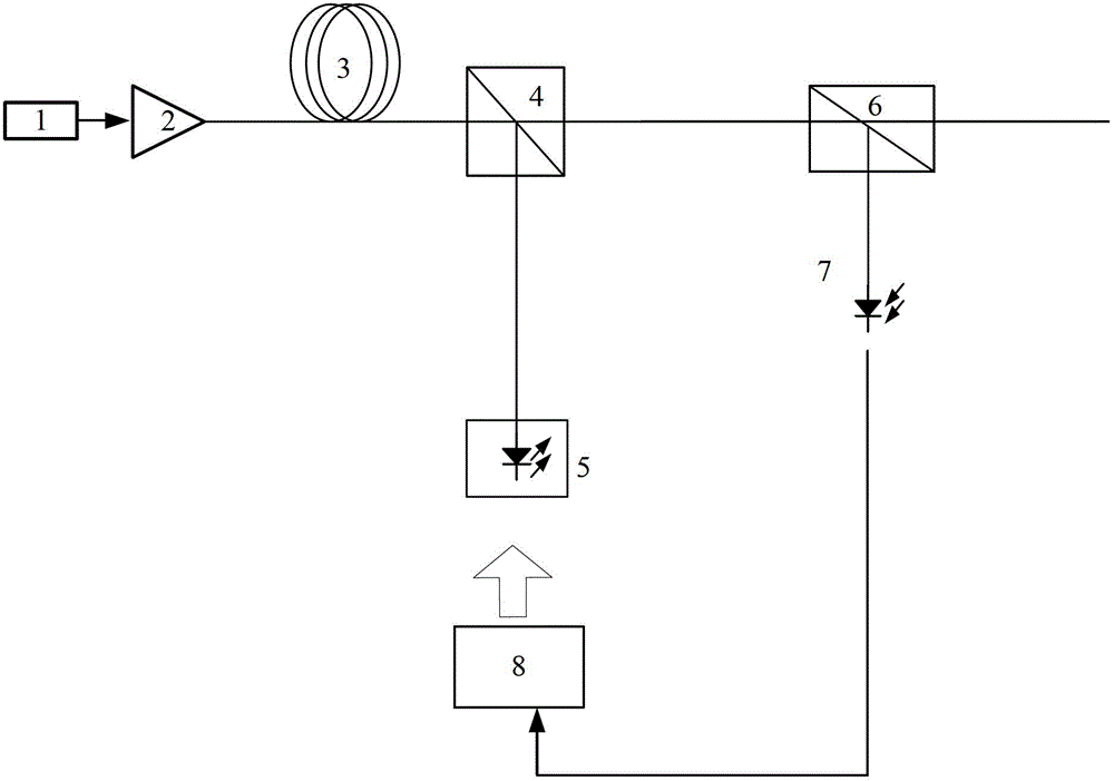
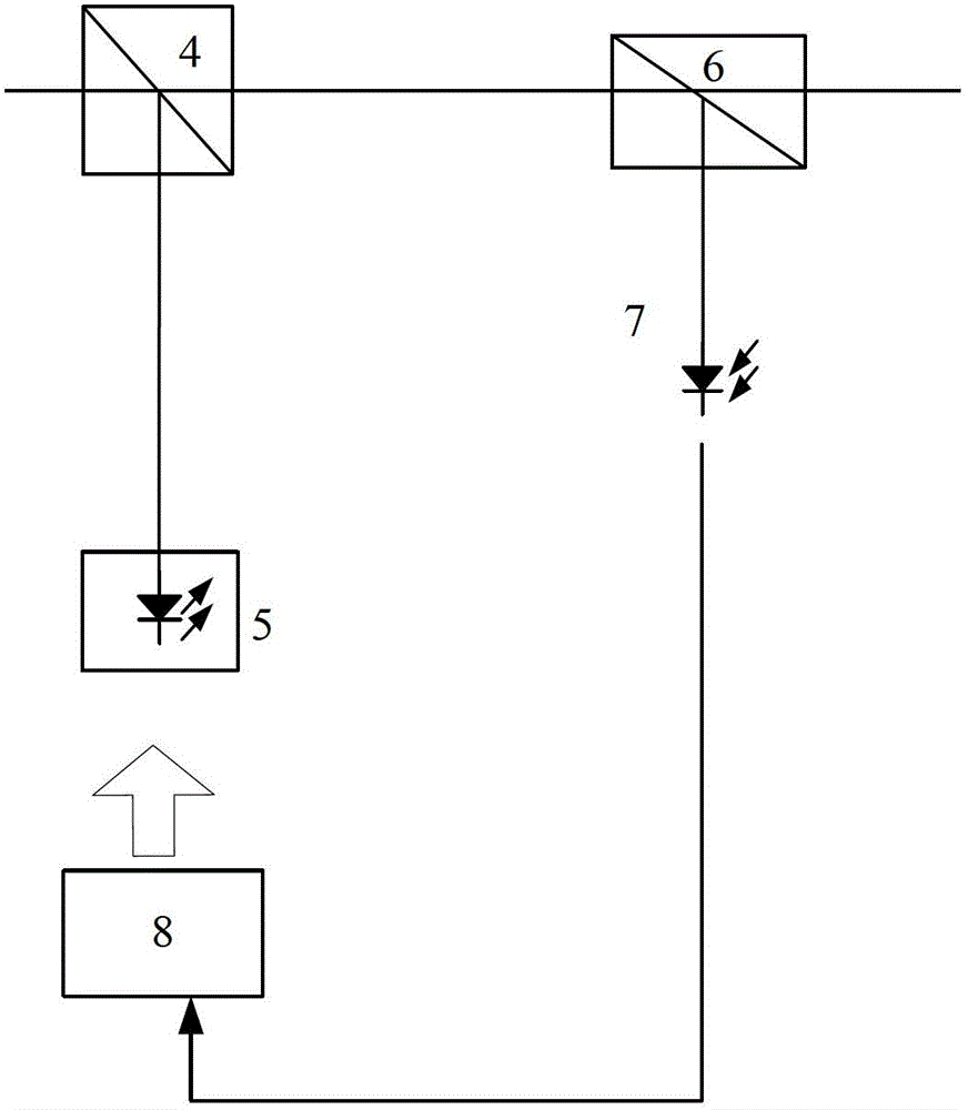
[0039] Such as figure 1 , figure 2 As shown, the Raman fiber amplifier of the present invention includes a pump signal combiner 4, a pump laser group 5, an out-of-band spontaneous emission amplification optical filter 6, a photodetector 7 and a control unit 8, wherein the The out-of-band spontaneous emission amplification optical filter 6 adopts a band-pass filter. The operating bandwidth of the out-of-band spontaneous emission amplification optical filter 6 adopts the working band for filtering out the signal light of the erbium-doped fiber amplifier 2, for being used in a system with monitoring light, the out-of-band spontaneous emission amplification optical filter 6 The working bandwidth adopts the working band for filtering out the signal light o...


PUM


Abstract

The invention relates to a Raman optical fiber amplifier and a detection method of loss of a transmission optical fiber connector of the Raman optical fiber amplifier. A transmission end (with a pumping signal multiplexer) of the amplifier is connected with a public end (with an out-of-band ASE (amplification of spontaneous emission) optical filter) of the amplifier, an out-of-band ASE output end of the out-of-band ASE optical filter is connected with a photoelectric detector, an output end of the photoelectric detector is connected with an input end of a control unit, an output end of the control unit is connected with an input end of a pumping laser device group, the pumping laser device group is connected with a pumping end of the pumping signal multiplexer, and a public end of the pumping signal multiplexer is connected with an input end of an erbium-doped fiber amplifier through a transmission optical fiber. The detection method comprises the following steps of: outputting a group of pumping light with determined power; determining a mathematic relation of out-of-band ASE optical power and pumping light power, and determining a mathematic relation of joint loss and the out-of-band ASE optical power; and determining a loss value of a joint. According to the Raman optical fiber amplifier and the detection method of the loss of the transmission optical fiber connector of the Raman optical fiber amplifier, disclosed by the invention, the gain and the gradient of the gain can be exactly controlled, the relative insertion loss of a transmission optical fiber line is known in real time, and performances of products can be improved.

Description

technical field [0001] The invention relates to a Raman fiber amplifier. In particular, it relates to a Raman optical fiber amplifier with a large gain control range and a detection method for transmission optical fiber joint loss. Background technique [0002] The communication system has higher and higher requirements on the control of Raman fiber amplifiers. Not only does it require that the gain of Raman fiber amplifiers can be adjusted in a wide range, but it also requires that the gain slope of Raman fiber amplifiers for multi-wavelength systems can also be adjusted in a wide range. At present, the Raman fiber amplifier mainly controls the gain through the mathematical relationship between the calibration gain and the power of amplified spontaneous emission (ASE) in a certain wavelength outside the signal working bandwidth. However, in the same type of optical fiber, due to the manufacturing process or batches, the attenuation of each optical fiber cannot be exactly t...

Claims


Application Information

Patent Timeline
Patent Type & Authority Applications(China)
IPC IPC(8): G02F1/39H01S3/108G01M11/02
Inventor 陶金涛乐孟辉付成鹏熊涛景运瑜江毅余春平
Owner GUANGXUN SCI & TECH WUHAN
Why Eureka
Try Eureka