High-power factor LED (light-emitting diode) driving circuit supporting silicon controlled rectifier dimming

A high power factor, LED driving technology, applied in the field of LED lighting, can solve the problems of low power factor and low circuit efficiency of low-power LED drivers, and achieve the effects of simple structure, improved reliability and small size

Inactive Publication Date: 2012-10-24
SHANGHAI UNIV +2
View PDF2 Cites 21 Cited by
  • Summary
  • Abstract
  • Description
  • Claims
  • Application Information

AI Technical Summary

Problems solved by technology

[0005] Aiming at the deficiencies existing in current thyristor dimming LED driver products, the purpose of the present invention is to solve the problems of low power factor and low circuit efficiency of current low-power LED drivers, and provide a high power factor LED that supports thyristor dimming The drive circuit, while supporting the mainstream triac dimmers, improves the power factor of the LED driver in the rated working state, and appropriately improves the working efficiency

Method used


Image

  • High-power factor LED (light-emitting diode) driving circuit supporting silicon controlled rectifier dimming
  • High-power factor LED (light-emitting diode) driving circuit supporting silicon controlled rectifier dimming
  • High-power factor LED (light-emitting diode) driving circuit supporting silicon controlled rectifier dimming

Examples


Embodiment 1

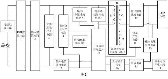
[0035] as attached figure 2 As shown, the high power factor LED drive circuit supporting silicon controlled rectifier dimming of the present invention includes an EMI filter circuit 1, an input rectifier circuit 2, a power factor correction circuit 3, a resistor divider sampling circuit 4, and a strong-weak divider discharge current Circuit 5, external RC oscillation circuit 6, input current sampling circuit 7, transformer primary clamp circuit 8, isolated high-frequency switching transformer 9, switching power supply management chip 10, VCC generation circuit 11, output rectification and filtering circuit 12, output voltage sampling Circuit 13, reference voltage generating circuit 14, comparator circuit 15 and photoelectric coupling circuit 16 are characterized in that:

[0036] The input end of the EMI filter circuit 1 is connected in series with a thyristor dimmer, connected to the AC mains, and the output end is connected to the input end of the input rectification circui...

Embodiment 2

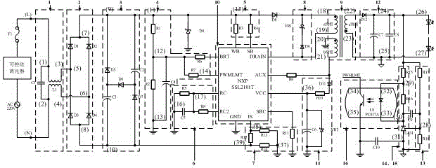
[0039] Embodiment two: as attached image 3 As shown, this embodiment is basically the same as Embodiment 1, and the special features are as follows:

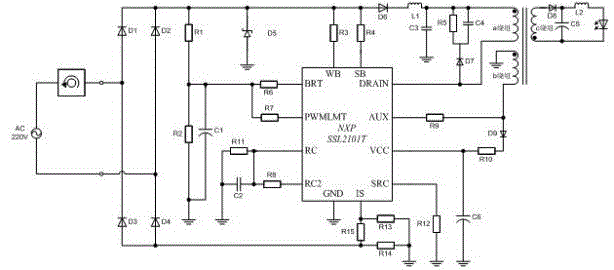
[0040] Described switching power supply management chip 10, uses the SSL2101T chip that NXP Company produces, and its pin is respectively WBLEED, SBLEED, VCC, GND, BRIGHTNESS, RC, RC2, PWMLIMIT, ISENSE, AUX, SOURCE, DRAIN, for convenience of description, Respectively abbreviated as WB, SB, VCC, GND, RC, RC2, PWMLMT, IS, AUX, SRC, DRAIN.

[0041] The EMI filter circuit 1 includes a capacitor C1 and a common-mode inductor L1. After connecting capacitor C1 in parallel at both ends (1) and (2) of the common-mode inductor L1, they are connected to the input terminals (L) and (N) of the LED drive circuit. terminal; the two ends of (3) and (4) of the common mode inductor are respectively connected to the input terminal (5) (6) of the input rectifier circuit 2.

[0042] The input rectifier circuit 2 includes a bridge rectifier compos...


PUM


Abstract

The invention relates to a high-power factor LED (light-emitting diode) driving circuit supporting silicon controlled rectifier dimming. A replacement type low-power LED driver implemented by the invention is an electrical isolation type circuit, the circuit adopts a flyback conversion topological structure, an isolation type transformer is used for performing energy storage and transmission, and an external three-end silicon controlled rectifier dimmer is used for dimming. In order to realize a dimming function, the use of a switching power supply management chip NXPSSL2101T integrating an MOSFET (metal oxide semiconductor field-effect transistor), the use of a three-end silicon controlled rectifier dimming switch for producing input signals, the use of a resistor voltage division way for producing brightness control signals and the like are considered. In order to realize a high power factor, the use of a valley-fill PFC (power factor correction) circuit is considered, and the valley-fill PFC circuit comprises three capacitors and two diodes. Under low-power limitation, the flyback conversion topological structure is adopted for realizing higher efficiency. The high-power factor LED driving circuit disclosed by the invention improves the circuit integration level, the power factor and the circuit conversion efficiency.

Description

technical field [0001] The invention relates to a high power factor LED drive circuit supporting silicon controlled rectifier dimming, in particular to a dimmable LED drive circuit based on an isolated flyback conversion topology and having a power factor correction circuit, belonging to LED lighting technology field. Background technique [0002] LED has the advantages of high luminous efficiency, long service life, and good stability, and is widely used in the field of lighting. [0003] The thyristor dimming technology of LED is developed by combining the traditional thyristor dimmer with the emerging LED driving technology, and is mainly used in the replacement LED lamp market. TRIAC dimmers are originally used for dimming incandescent and fluorescent lamps. In the process of promoting LED lighting, it is required that the infrastructure of the existing lighting system cannot be changed. Therefore, if LED lamps can be dimmed using existing TRIAC dimmers, the barriers ...

Claims


Application Information

Patent Timeline
Patent Type & Authority Applications(China)
IPC IPC(8): H05B37/02
Inventor 刘廷章曹凌云杨卫桥周颖圆乔波姚丽霞
Owner SHANGHAI UNIV
Why Eureka
Try Eureka