Filling mould module and construction method thereof

A construction method and filling mold technology, which can be applied to building components, walls, floors, etc., can solve the problems of volume limitation, reduce concrete performance, increase cost, etc., and achieve the effect of facilitating factory production, reducing panel costs, and saving labor costs.

Active Publication Date: 2014-04-09
盐城市双新建设投资有限公司
View PDF8 Cites 0 Cited by
  • Summary
  • Abstract
  • Description
  • Claims
  • Application Information

AI Technical Summary

Problems solved by technology

The existing problem is that, with the shortage of human resources in our country, the cost of labor has doubled, and the cost of the existing filling wall has been greatly improved. In addition, the low strength of the filling wall of aerated concrete blocks is not conducive to safety and security. Painting, its heavy weight will increase the cost of the main structure, and its poor integrity is not conducive to the earthquake resistance of the structure, while the construction process of the hollow inner mold metal mesh cement inner partition wall is complicated and the construction period is longer
The main problems in the existing technology: firstly, the anti-floating problem of the filling mold. The existing various filling molds all use thin walls and cavities to reduce the self-weight load of the floor. In order to prevent the filling mold from floating when pouring concrete, various Fixing measures, one measure is to use thick steel bars to connect the filling formwork with the steel mesh of the structure, and use the self-weight of the steel mesh to increase the anti-floating ability of the filling formwork. This method is not only complicated and labor-intensive, but also requires a large amount of steel and costs High, sometimes it will make the steel mesh of the structure float together, affecting the quality of structural engineering
Another measure is to use thick iron wires or bolts for the base to fix the filling form on the bottom formwork. This method is not only complicated and labor-intensive and costly, but also time-consuming and labor-intensive when removing the formwork will damage the bottom formwork and reduce its repetition. Utilization rate, thereby increasing the amortization cost of the bottom mold and the cost of demoulding
Another main problem existing in the prior art is: the concrete maintenance problem of the hollow slab structure, because the section thickness of the hollow slab is relatively large, and the upper thin slab and the lower thin slab and the dense rib are all separated by the filling form, the watering during construction The maintenance can only be carried out from above, and only the concrete of the upper thin slab can be fully cured, so the quality of the concrete of the dense ribs and the bottom thin slab is seriously affected, and its strength often does not meet the requirements, and shrinkage cracks are prone to occur
Another main problem existing in the prior art is: the construction method problem of the hollow slab concrete. Because the characteristics of the concrete hollow slab structure are that the section thickness is large, the interior is empty, and the upper and lower concrete slabs and dense ribs are separated by the filling form, the bottom slab concrete is very Thin (generally 50mm) and cannot be vibrated with a vibrating rod, the construction is very difficult. The existing construction method is one-time pouring and one-time forming. The dense ribs of the hollow slab and the thin-slab concrete on the bottom mainly rely on the high slump performance of the concrete itself. However, the high slump performance of concrete will increase the amount of cement and admixture, which will increase its cost, increase shrinkage deformation and easily produce shrinkage cracks, thereby reducing the performance of concrete. The occurrence of honeycomb, pockmarks, dog holes and leaked pouring still occurs frequently, making it difficult to guarantee the quality of the hollow board
Another main problem existing in the prior art is: due to the artificial short-distance handling problem of the filling mold, its dead weight is limited to a certain extent, so its volume is limited, which affects its fasting rate and economic indicators.

Method used


Image

  • Filling mould module and construction method thereof
  • Filling mould module and construction method thereof
  • Filling mould module and construction method thereof

Examples


Embodiment 1

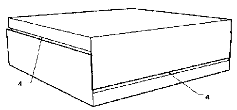
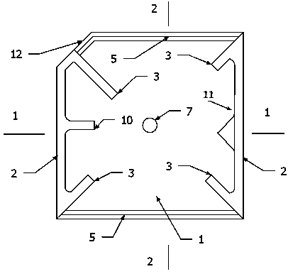
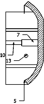
[0043] Embodiment 1: as Figure 2 ~ Figure 4 The filling mold module shown includes a panel 1, a side panel 2, and a docking panel 3. The docking panel and the side panel are perpendicular to the panel, and the angle between the connecting panel and the side panel is 45 degrees. The two modules face each other to form a curing joint. The free edge of side plate 2 is the slope of 45 degrees inwards. The two free edges of the panel 1 are provided with convex ribs 5 with an outer slope of 45 degrees. The inner surface of the panel 1 is concave, and the outer surface is convex. The inner surface of the panel 1 is connected with a pillar 7 in the center, and the height of the pillar 7 is half of the height of the side plate 2 . The inner surface of the panel 1 and the space between the side panels 2 are filled with thermal insulation materials, and the filling height is no more than half of the height of the side panels 2 . There is a stiffening rib 10 perpendicular to the panel ...

Embodiment 2

[0045] Embodiment 2: as Figure 2 ~ Figure 4 The filling mold module shown includes a panel 1, a side panel 2, and a docking panel 3. The docking panel and the side panel are perpendicular to the panel, and the angle between the connecting panel and the side panel is 45 degrees. The two modules face each other to form a curing joint. The free edge of side plate 2 is the slope of 45 degrees inwards. The two free edges of the panel 1 are provided with convex ribs 5 with an outer slope of 45 degrees. The inner surface of the panel 1 is concave, and the outer surface is convex. The inner surface of the panel 1 is connected with a pillar 7 in the center, and the height of the pillar 7 is half of the height of the side plate 2 . The inner surface of the panel 1 and the space between the side panels 2 are filled with thermal insulation materials, and the filling height is no more than half of the height of the side panels 2 . There is a stiffening rib 10 perpendicular to the panel ...

Embodiment 3

[0047] Embodiment 3: as Figure 5 ~ Figure 6 The filling mold module shown includes panel 1, side panel 2, butt panel 3, the butt panel and the side panel are perpendicular to the panel, the angle between the panel and the side panel is 45 degrees, and the two modules are oppositely butted to form a curing joint, the side panel The free edge of 2 is an inward 45-degree slope. The two free edges of the panel 1 are provided with convex ribs 5 with an outer slope of 45 degrees. A transverse supporting rib 9 perpendicular to the side plate 2 is connected between the inner surface of the panel 1 and the side plate 2 , and its height is half of the height of the side plate 2 . The inner surface of the panel 1 is connected with a vertical support rib 8 parallel to the side plate 2 , and its height is half of the height of the side plate 2 . The inner surface of the panel 1 and the space between the side plates 2 are filled with thermal insulation materials, and the filling height m...


PUM


Abstract

The invention provides a filling mould module and a construction method of the filling mould module. The filling mould module comprises a panel (1), a side plate (2) and an abutting plate (3), wherein convex ribs (5) with 45-degree outer inclined surfaces are arranged on two free sides of the panel (1); the abutting plate (3) and the side plate (2) are vertical to the panel (1), and the included angle formed by the abutting plate (3) and the side plate (3) is 45 degrees; and two modules are abutted face to face to form a maintenance seam (4). In a construction process of floors, single box body or four box bodies as a group are firmly arranged in a horizontal dual-direction clearance manner or one-way clearance one-way tight manner; and the clearance is paved with reinforcement, and then cast with concrete. In the construction process of the wall body, two modules are rotated by 90 degrees face to face to be buckled together to be a box-shaped building block; and the box-shaped building block is built by staggering one half of the width on each layer. The filling mould module and the construction method of the filling mould module have the advantages of being high in the industrialization production degree and simple in filed construction process, thereby the defects of long working period, complicated process and the like in the prior art are made up.

Description

technical field [0001] The invention relates to a building floor slab or a filling wall and a construction method thereof, in particular to a concrete hollow floor slab or a combined box block filling wall and a construction method thereof. Background technique [0002] The building filling wall is the maintenance structure of the building, with a large amount and a wide area. Its sound insulation, heat insulation, strength, fire prevention, moisture resistance, waterproof and other properties directly affect the use performance and safety performance of the building. With the progress of the times and the requirements of environmental protection, the era of Qin bricks and Han tiles has come to an end, and new wall materials have been introduced continuously. At present, aerated concrete blocks are mostly used as filling walls. In addition, the hollow inner mold metal mesh cement inner partition wall is also widely used. The existing problem is that, with the shortage of hu...

Claims


Application Information

Patent Timeline
Patent Type & Authority Patents(China)
IPC IPC(8): E04B5/36E04B2/00E04G21/00
Inventor 谢孟谢琦
Owner 盐城市双新建设投资有限公司
Why Eureka
Try Eureka