Medium frequency induction welding method of rail

A technology for induction welding and rails, which is applied to rails, welding equipment, rails, etc., can solve the problems of large influence of human factors, difficulty in realizing accurate measurement and control of rail temperature, and difficult quality control, so as to ensure the quality of welds and their Stability, convenient for automatic assembly line production, and realize the effect of automatic assembly line production

Inactive Publication Date: 2012-11-14
INST OF SCI & TECH SHENYANG RAILWAYBUREAU +1
View PDF6 Cites 12 Cited by
  • Summary
  • Abstract
  • Description
  • Claims
  • Application Information

AI Technical Summary

Problems solved by technology

However, there are gray spots in the weld structure in flash welding, which cannot be avoided. When the area of ​​gray spots exceeds a certain level, the welding head will be scrapped and the mechanical properties of the weld will be seriously reduced; in addition, the welding power required by flash welding is high, and the welding machine cost Very high (take GAAS80 fixed welding machine as an example, its cost is about 12 million, plus the total price of accessories is as high as 17 million), once the welding machine breaks down or needs to replace accessories, it will cause great losses and seriously affect production efficiency
[0005] 3. Arc welding: a welding method that uses an arc as a heat source to melt the electrode metal and fill it to form a weld. It has a high degree of manual work, low produc

Method used


Image

  • Medium frequency induction welding method of rail
  • Medium frequency induction welding method of rail
  • Medium frequency induction welding method of rail

Examples


Embodiment 1

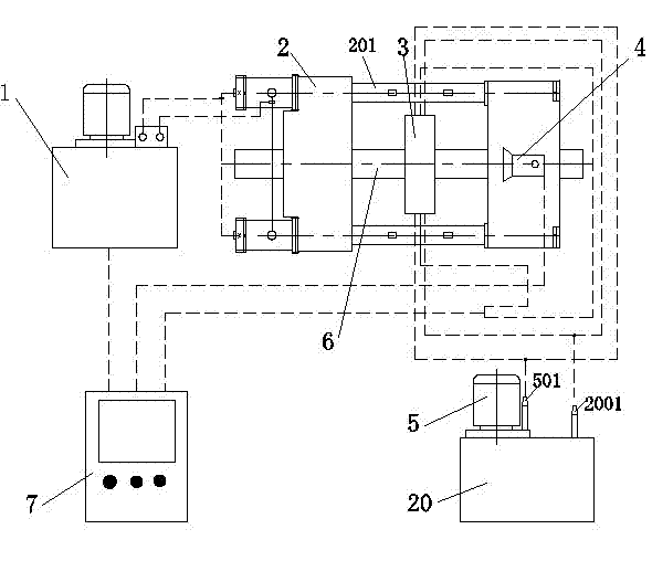
[0035] As shown in the figure, the present invention adopts an intermediate frequency induction heating method, based on the principle of pressure welding, through welding upsetting to make the two rails to be welded into one body, which specifically includes the following steps (take U71Mn rail as an example):

[0036] 1. Preparation before welding. Grind the end surface of the rail 6 to be welded with a grinder, and use a clean file to manually fine file. The file cleaning agent uses carbon tetrachloride. The surface roughness of the polished rail end surface is Ra12.5 microns, and the end surface flatness and the tolerance of the perpendicularity between the end surface and the rail axis are 0.15 mm.

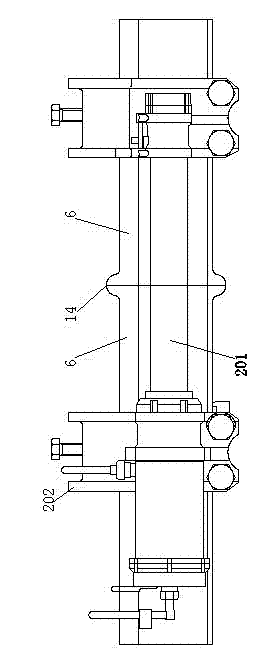
[0037] 2. Use the air pressure welding and crimping machine 2 to clamp the steel rail 6 to be welded, and adjust the relative position of the two steel rails 6 to be welded so that the end faces to be welded are aligned. The air pressure welding and crimping machine 2 is connecte...

Embodiment 2

[0049] The medium frequency induction welding method of the steel rail specifically includes the following steps (take U75V steel rail as an example):

[0050] 1. Preparation before welding.

[0051] 2. Clamp the rail 6 to be welded by the air pressure welding and crimping machine 2.

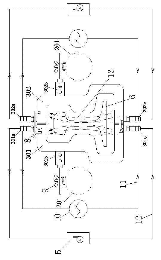
[0052] 3. Support the intermediate frequency sensor 3 on the two guide posts 201 of the air pressure welding and crimping machine 2, and make the intermediate frequency sensor 3 surround the welding end faces of the two steel rails 6 to be welded. Adjust the left, right, upper and lower gaps between the intermediate frequency inductor 3 and the steel rail 6 to be welded to 29mm.

[0053] 4. The intermediate frequency sensor 3 is connected with a water cooling system, and the power supply of the water cooling system is turned on to supply circulating cooling water to the intermediate frequency sensor 3.

[0054] 5. Rail pre-top.

[0055] 6. The intermediate frequency inductor 3 is used to heat the end surf...

Embodiment 3

[0062] The medium frequency induction welding method of the steel rail specifically includes the following steps (take PG4 rail as an example):

[0063] 1. Preparation before welding.

[0064] 2. Clamp the rail 6 to be welded by the air pressure welding and crimping machine 2.

[0065] 3. Support the intermediate frequency sensor 3 on the two guide posts 201 of the air pressure welding and crimping machine 2, and make the intermediate frequency sensor 3 surround the welding end faces of the two steel rails 6 to be welded. Adjust the left, right, upper and lower gaps between the intermediate frequency sensor 3 and the steel rail 6 to be welded to 31mm.

[0066] 4. The intermediate frequency sensor 3 is connected with a water cooling system, and the power supply of the water cooling system is turned on to supply circulating cooling water to the intermediate frequency sensor 3.

[0067] 5. Rail pre-top.

[0068] 6. The intermediate frequency inductor 3 is used to heat the end surface area ...


PUM


Abstract

The invention discloses a medium frequency induction welding method of a rail. The medium frequency induction welding method is characterized by comprising the following steps: 1. a rail to be welded is clamped by utilizing a gas pressure welding clamping machine; the end surface area to be welded of the rail to be welded is heated by a medium frequency inductor; in the heating process, an infrared thermometer is used for detecting whether the heating temperature of the end surface area to be welded reaches a welding upsetting initial temperature or not; and the medium frequency inductor is connected with a medium frequency power source and a water cooling system; and 2. the welding upsetting of the rail to be welded is realized. Through the medium frequency induction welding method disclosed by the invention, in a welding process, the welding upsetting temperature is accurately controlled; the interference of anthropic factors on the welding quality is eliminated to a maximum extent; the stability is high; foundry defects and flash welding ash spots are not generated; and when the welding quality is guaranteed, the automatic flow line production is conveniently realized and the welding production efficiency is favorably improved.

Description

Technical field [0001] The invention relates to a steel rail welding technology, in particular to a steel rail intermediate frequency induction welding method. Background technique [0002] In the rail welding technology, the requirements for the mechanical properties, geometric accuracy and quality stability of the weld are very high, and the quality of the welding seriously affects the service life of the rail. At present, there are four main welding methods for rails: [0003] 1. Thermite welding: use thermite reaction heat as a heat source to make the thermite flux into liquid metal, and inject sand to form weld metal. Since the weld is a cast welded structure, there are unavoidable casting defects such as porosity, inclusions, slag inclusion, and shrinkage. Its mechanical properties are much lower than that of the rail base material, and the plasticity and toughness of the weld are low. [0004] 2. Flash welding: When the current passes through the contact surfaces of the two ...

Claims


Application Information

Patent Timeline
IPC IPC(8): B23K28/00B23K101/26
Inventor 陶毅王子儒宋玉泉翟峰李琦张君袁学勇于国英
Owner INST OF SCI & TECH SHENYANG RAILWAYBUREAU
Why Eureka
Try Eureka