Method for controlling attitude of aircraft based on L1 adaptive control
What is Al technical title?
Al technical title is built by PatSnap Al team. It summarizes the technical point description of the patent document.
An adaptive controller and adaptive control technology, applied in attitude control and other directions, can solve problems such as the influence of control effects
Inactive Publication Date: 2012-12-05
BEIJING INSTITUTE OF TECHNOLOGYGY
View PDF4 Cites 49 Cited by
Summary
Abstract
Description
Claims
Application Information
AI Technical Summary
This helps you quickly interpret patents by identifying the three key elements:
Problems solved by technology
Method used
Benefits of technology
Problems solved by technology
[0004] Model-based nonlinear control algorithms, such as sliding mode controllers and backstepping methods, w
Method used
Image
Click on the blue label to locate the original text in one second.
Reading with bidirectional positioning of images and text.
Examples
example 1
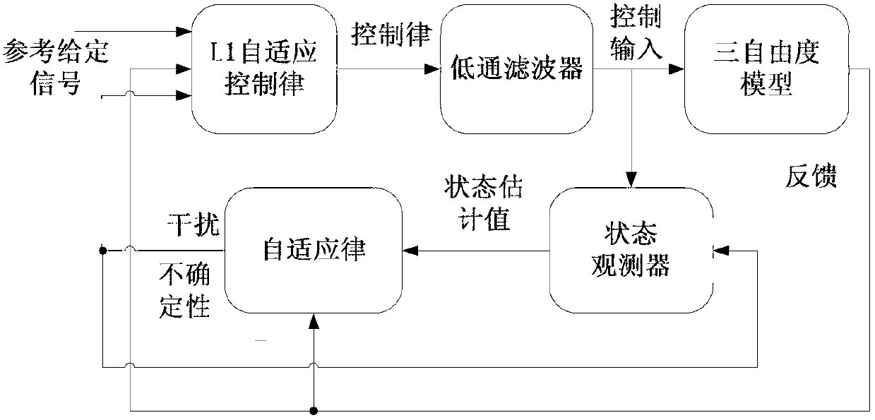
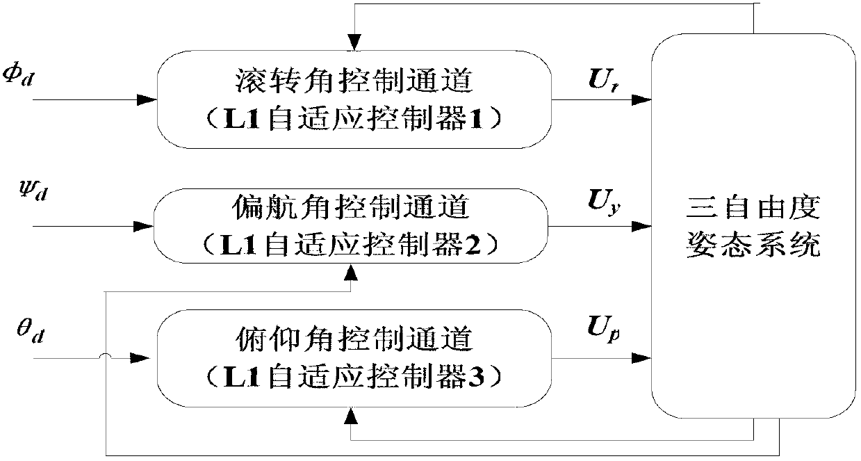
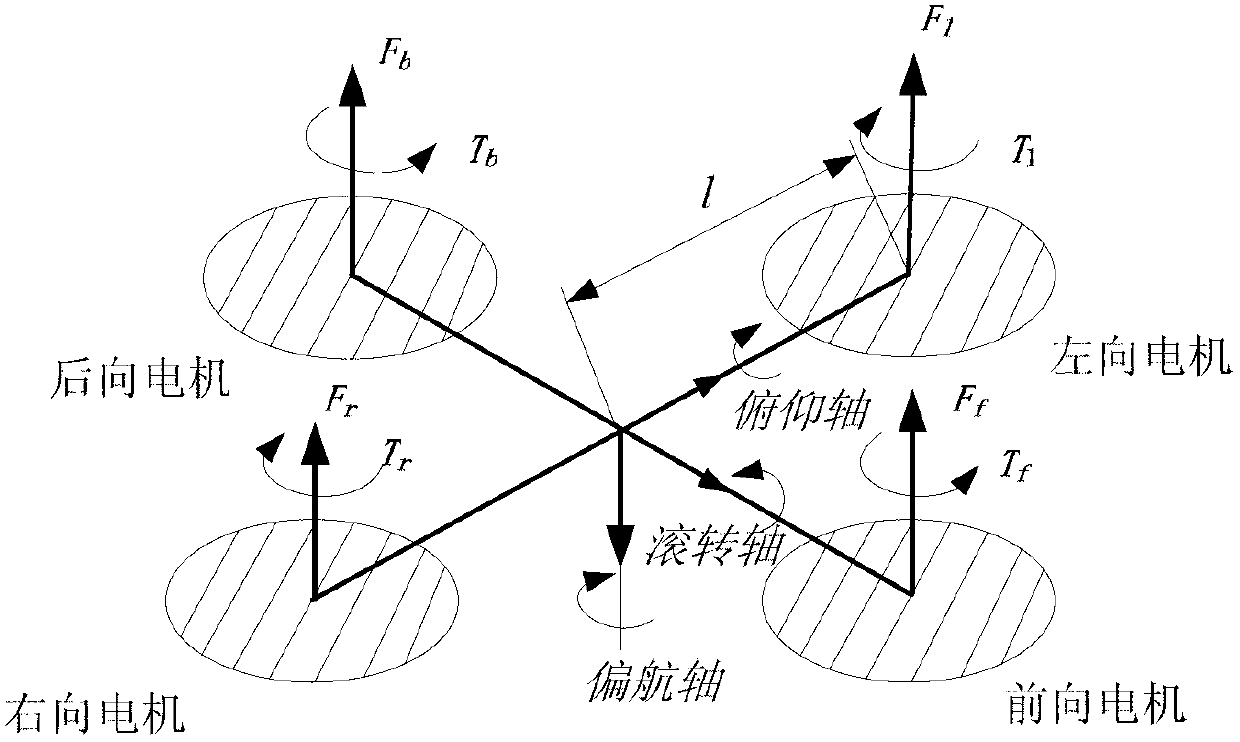
[0054] Example 1: The L1 adaptive attitude control method designed in the present invention is verified by the four-rotor suspension control platform of Quanser. Such as image 3 As shown, the speed difference between the forward motor and the backward motor in the quadrotor system will drive the quadrotor system to make a pitch motion around the pitch axis; the speed difference between the left motor and the right motor will drive the quadrotor system to move around the roll axis. Rolling attitude movement; the front and rear motors rotate in reverse, and the left and right motors rotate forward. When the torque generated by the two pairs of motors is unbalanced, the quadrotor system will have yaw motion. In short, the entire system adjusts the attitude of the system by adjusting the input of the drive motors of the four propellers and changing the speed of the four propellers to change the force and torque on the system. The closed-loop structure frame of the whole system ...
example 2
[0071] Example 2: The structure of the hardware part of the control system is as follows: Figure 7 shown. Among them, the main controller 1 adopts ATmega2560 of AVR, which has higher cost performance and is easier to design in the motor control part. The attitude information of the quadrotor is realized by the inertial measurement unit, the gyroscope 11 adopts the gyroscope IDG500 and ISZ500, the accelerometer 10 adopts the ADXL335, and the three-axis angular velocity value and the three-axis angular acceleration value measured by the gyroscope and the accelerometer are transmitted through the analog-to-digital converter 9. Give the main controller 1, and finally give the current attitude of the quadrotor through attitude calculation. The control signal of the remote controller 4 is sent to the PPM decoder 2 through the receiver 5 of 8 channels, and the remote controller signal and the autopilot signal are selected through the multiplexer 3, and the selection control signal ...
PUM
Abstract
The invention relates to a method for controlling an attitude of an aircraft based on L1 adaptive control, and belongs to the technical field of automatic unmanned aircraft attitude control. The method comprises the following steps of: inputting a control signal u(t) of a system into a state observer to acquire an aircraft state estimated value, taking the aircraft state estimated value as the input of an adaptive law to acquire the uncertainty of the system and an estimated value of external disturbance, inputting a set reference signal r(t) into an adaptive control law to acquire a system adaptive control law, inputting the system adaptive control law into a low-pass filter to acquire a control signal u2(t), superposing the control signal u2(t) with a linear state feedback control law u1(t), inputting the control signal u2(t) into the state observer, applying the control signal u2(t) to a controlled object, feeding an actual attitude value x(t) back to the adaptive law, the adaptive control law and the state observer by the controlled object, and thus forming an L1 adaptive closed-loop control system. Aircraft attitude L1 adaptive control established by the method is high in robustness and good in stabilizing and adjusting effects on aircraft attitude systems with nonlinearity, coupling disturbance and environmental disturbance.
Description
technical field [0001] The invention relates to an aircraft attitude control method based on L1 adaptive control technology, and belongs to the technical field of unmanned aircraft attitude automatic control. Background technique [0002] Unmanned Aerial Vehicle (UAV), referred to as UAV, is a kind of unmanned aerial vehicle that is powered, controllable, can carry multiple mission equipment, perform multiple tasks, and can be reused. In view of its unique advantages such as low cost, low loss, zero casualties, reusability and high maneuverability, the scope of use has been expanded to three major fields: military, civilian and scientific research. In the military, it can be used for reconnaissance, surveillance, communication relay, electronic countermeasures, fire guidance, battle result assessment, harassment, temptation, ground (sea) attack, target simulation and early warning, etc.; in civilian use, it can be used for geodesy, meteorology Observation, urban environment...
Claims
Application Information
Patent Timeline
Application Date:The date an application was filed.
Publication Date:The date a patent or application was officially published.
First Publication Date:The earliest publication date of a patent with the same application number.
Issue Date:Publication date of the patent grant document.
PCT Entry Date:The Entry date of PCT National Phase.
Estimated Expiry Date:The statutory expiry date of a patent right according to the Patent Law, and it is the longest term of protection that the patent right can achieve without the termination of the patent right due to other reasons(Term extension factor has been taken into account ).
Invalid Date:Actual expiry date is based on effective date or publication date of legal transaction data of invalid patent.