Concentration system for rapidly concentrating slurry

A concentration system and fast technology, applied to loose filter material filters, filtration separation, separation methods, etc., can solve the problems of long concentration cycle, high concentration requirements, and large concentration cycle, so as to avoid clogging failure and improve The effect of concentration efficiency

Active Publication Date: 2012-12-12
HOHAI UNIV
View PDF6 Cites 13 Cited by
  • Summary
  • Abstract
  • Description
  • Claims
  • Application Information

AI Technical Summary

Problems solved by technology

[0003] Conventional thickening equipment is often used in the treatment of sewage plant sludge, but due to the large output of engineering mud, the fast occurrence speed, and high concentration requirements, it is difficult for conventional thickening equipment to meet the requirements in terms of processing capacity
The conventional concentration technology refers to the gravity concentration method that puts the sludge in the concentration tank and uses the relative density difference between the solid particles in the sludge and the water to realize the separation of the mud and water. The conventional concentration equipment is composed of a reinforced concrete concentration tank, a central mud inlet pipe , supernatant overflow weir, sediment discharge pipe, mud scraper, stirring grid, the operating load is generally 50 ~ 90 kg / m 2 d, the concentration cycle is longer than 12 h, and the concentration cycle is long

Method used


Image

  • Concentration system for rapidly concentrating slurry
  • Concentration system for rapidly concentrating slurry
  • Concentration system for rapidly concentrating slurry

Examples


Embodiment Construction

[0022] The present invention will be further described below in conjunction with the accompanying drawings.

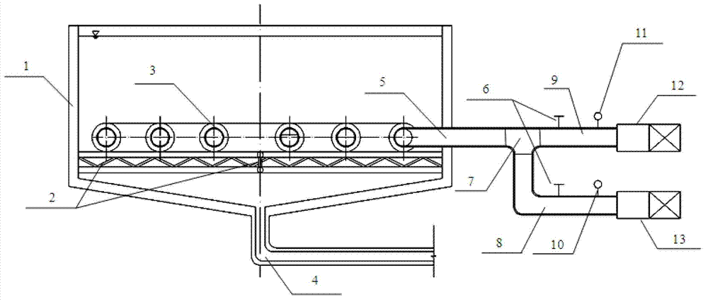
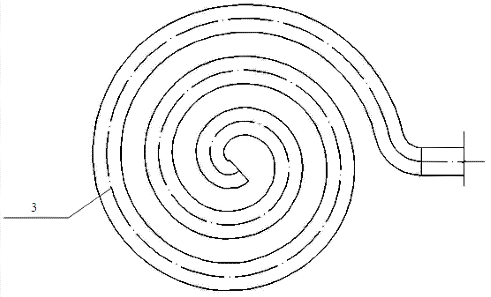
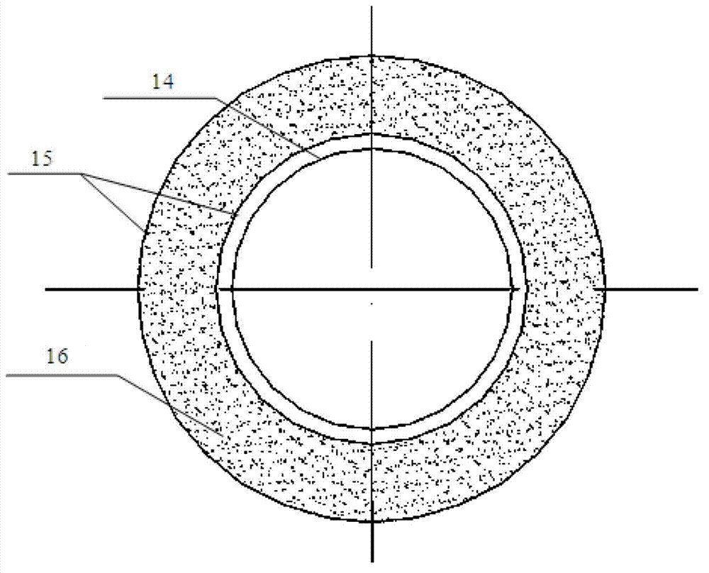
[0023] figure 1 : The present invention is used for the thickening system structure schematic diagram of quick thickening of mud, figure 2 : Schematic diagram of the structure of the vacuum filter tube, image 3 : Schematic diagram of the section of the vacuum filter tube. refer to Figure 1-3 , a concentration system for rapid concentration of mud, including a concentration tank 1 and a mud pumping pipeline 4 located below the concentration tank 1, the upper part of the concentration tank 1 is cylindrical, the lower part is funnel-shaped, the effective depth is 6m, and the diameter is 7m. The slope of the bottom of the concentration tank 1 is set to 1:5, and the vacuum suction filter tube 3 is fixed at a distance of 1.5m from the bottom of the tank; a support 2 is set on the side wall of the concentration tank, and the support 2 is composed of a cross-shaped steel...


PUM

PropertyMeasurementUnit
diameteraaaaaaaaaa
densityaaaaaaaaaa

Abstract

The invention provides a concentration system for rapidly concentrating slurry, comprising a cylindrical concentration tank and a slurry pumping pipeline located at the bottom of the cylindrical concentration tank, wherein a vacuum filtration pipe is arranged at the part of the concentration tank, which is 1 / 3-1 / 5 of the depth from a tank bottom; the bracket is arranged on a side wall of the concentration tank and is used for supporting the vacuum filtration pipe; an external connector of the vacuum filtration pipe is arranged on the wall of the concentration tank; the vacuum filtration pipe extends out of the concentration tank through the external connector of the vacuum filtration pipe, and is connected with an air compressor through a three-way connector and a vacuumizing device; a valve and a vacuum meter are arranged on a water guide pipe between the three-way connector and the vacuumizing device; and a valve and an air pressure meter are arranged on an air pumping pipe between the three-way connector and the air compressor. The vacuum filtration pipe is in a spiral annular shape and is wound in the same plane; a gap of 50-60 cm is reserved between a pipeline of the outermost ring and the tank wall of the concentration tank; and compared with a method for purely utilizing self-gravity effect to realize slurry concentration, the concentration system provided by the invention can realize the slurry concentration by the combined action of gravity and negative-pressure pressure difference, so that the concentration efficiency is greatly improved.

Description

technical field [0001] The invention relates to mud concentration treatment technology, in particular to a thickening system for rapid mud concentration. Background technique [0002] In order to improve the water quality of rivers and lakes and ensure the normal flood discharge capacity and navigation capacity of rivers, large-scale dredging and dredging projects are being carried out in lakes and rivers in our country. At the same time, when the mud-water shield is used in the excavation of urban tunnel projects, a large amount of waste engineering mud will be produced. These engineering muds have high moisture content and low density, so they are difficult to use directly. The existing treatment methods include mud-water separation technology through cyclone separation, plate and frame filter press, or sedimentation and storage technology in the stockyard. Most of these technologies have problems such as occupying a large area of ​​land, high processing costs, and large ...

Claims


Application Information

Patent Timeline
Patent Type & Authority Applications(China)
IPC IPC(8): B01D36/04B01D24/04
Inventor 朱伟周宣兆闵凡路钟小春吕一彦王升位
Owner HOHAI UNIV
Why Eureka
Try Eureka