Manipulator unit and production line with same

A technology of manipulators and racks, applied in the field of manipulator units and production lines with the manipulator units, can solve the problems of inability to adapt to large-scale industrial production, low work efficiency, poor working environment, etc., to ensure smooth operation, convenient operation, and easy operation The effect of accurate position

Inactive Publication Date: 2012-12-19
TIANJIN TASLY PHARMA CO LTD
View PDF8 Cites 4 Cited by
  • Summary
  • Abstract
  • Description
  • Claims
  • Application Information

AI Technical Summary

Problems solved by technology

The working environment is poor, the work intensity is high and the work efficiency is extremely low, which cannot meet the requirements of industrialized mass production
At the same time, the outlet of some heat shrink sealing machines is aligned

Method used


Image

  • Manipulator unit and production line with same
  • Manipulator unit and production line with same
  • Manipulator unit and production line with same

Examples


Embodiment 1

[0056] Power source embodiment one, servo motor + cylinder type

[0057] Figure 13 It is a schematic diagram of the overall structure of an embodiment of the power source of the present invention. Such as Figure 13As shown, in the present embodiment, the horizontal motion is controlled by the servo motor 50, the rotary motion becomes linear motion easily and simply, the operation is stable and reliable, there is no impact, the noise is low, and the most important thing is strong controllability. The cylinder is used for vertical movement, the linear movement is directly realized, the structure is simple, time-saving and there is no impact source here, so the noise and vibration are not large. The cylinder 55 realizes the connection with the splint mechanism through the bearing seat and the bearing seat pillar, and the guide rod ensures the reliability of the horizontal movement. The cylinder 55 is fixed on the fixed plate 3 and is connected with the fork of the splint mec...

Embodiment 2

[0058] Power source embodiment two, double servo motor type

[0059] Figure 14 It is a schematic diagram of the overall structure of Embodiment 2 of the power source of the present invention. Such as Figure 14 As shown, in this embodiment, dual servo motors 50 are adopted, the controllability is the best, the structure is the simplest and the operation is reliable.

Embodiment 3

[0060] Power source embodiment three, single servo motor + rack and pinion type

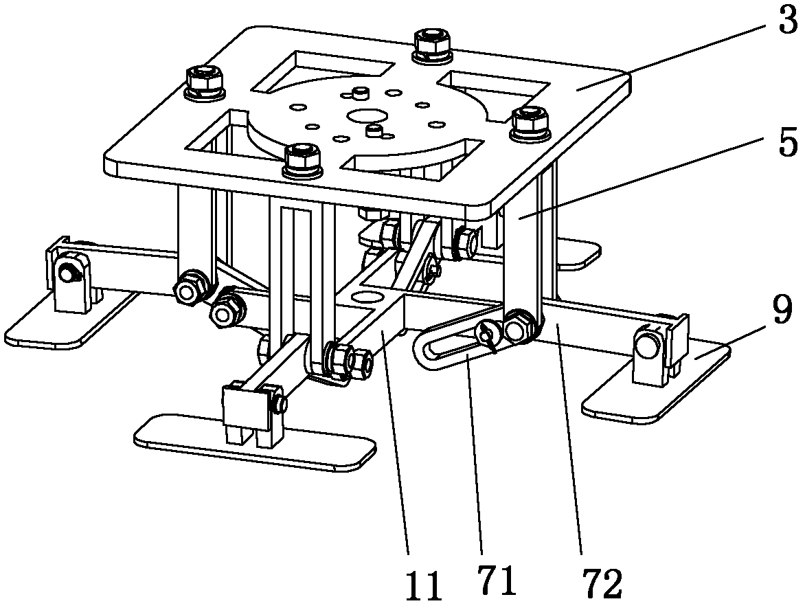
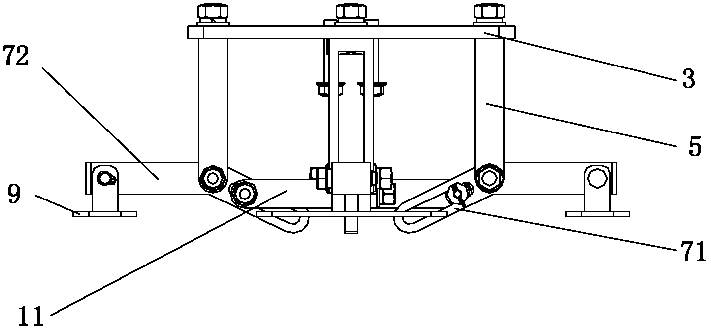
[0061] Figure 15 and Figure 16 They are the overall structure schematic diagram and partial structure schematic diagram of the third embodiment of the power source of the present invention, respectively. Such as Figure 15 and combine Figure 16 As shown, the present embodiment adopts a single servo motor 50, which saves one power source, and the rotational motion is separated into horizontal motion and vertical motion through the clutch and the brake. Turning rotary motion into linear motion, the cost is relatively low; there is no noise and impact phenomenon, and the operation is reliable.

[0062] The specific action process of this embodiment is as follows:

[0063] First of all, the manipulator is in a static standby state above the middle bag pallet 13 . Now the horizontal movement clutch 61 loses power and disengages, the vertical movement clutch 63 is energized and sucked in, the ...


PUM


Abstract

The invention provides a manipulator unit which comprises a machine frame, a power source and a control device, wherein the power source and the control device are connected, and the power source is controlled via the control device; a clamp plate device is arranged on the machine frame, and comprises a fixing plate on which a supporting rod is arranged; the supporting rod is hinged with a clamp plate arm; the clamp plate arm comprises an upper clamp plate arm and a lower clamp plate arm; an opening groove is arranged at the upper clamp plate arm, and a clamp plate is arranged at the tail end of the lower clamp plate arm; one end of a shifting fork is arranged in the opening groove of the upper clamp plate groove in a manner of slipping, and while the other end of the shifting fork is connected with a first power source and driven by the first power source to move in a vertical direction by a reciprocating way; the fixing plate is connected with a second power source, and the clamp plate drive is driven to upwards move in the level direction by the reciprocating way through the fixing plate; and a working channel is also arranged on the machine frame. A production line is structured as follows: the manipulator units are arranged at intervals in a conveyor belt; and a baffle plate is arranged between the working channels of two adjacent manipulator units. The manipulator unit and the production line have simple structures, can be operated conveniently, and have accurate working positions; the products are shaped during being picked; and with adoption of the manipulator unit and the production line, the continuous production can be achieved along with high production efficiency and high controllability can be ensured.

Description

technical field [0001] The invention relates to a manipulator unit and a production line with the manipulator unit, belonging to the technical field of mechanical manufacturing. Background technique [0002] In the existing automatic product outsourcing production line, the heat shrink sealing machine shrinks and seals the finished small boxes of multiple products with transparent plastic packaging materials into a middle bag, and the middle bag falls on the conveyor belt, and then conveys it to the next station for processing. The next step of the process. According to the transmission speed requirements of the conveyor belt, the speed at which finished products fall onto the conveyor belt is generally required to be 25 packs / min. In addition, since the shape of the shrink-sealed tundish is not neat, it needs to be reshaped and arranged into a regular rectangle. [0003] According to the needs of the site and output, the existing production workshop usually sets up multip...

Claims


Application Information

Patent Timeline
IPC IPC(8): B65B61/24B65B61/00
Inventor 李国华杨德燕李常洪古春杰季永斌
Owner TIANJIN TASLY PHARMA CO LTD
Why Eureka
Try Eureka