Eureka AIR delivers breakthrough ideas for toughest innovation challenges, trusted by R&D personnel around the world.

Robot single joint hydraulic pressure and position control test platform

A single-joint, hydraulic pressure technology, applied in the direction of electrical testing/monitoring, etc., can solve the problems of single-joint hydraulic pressure and position control of robots that have not been seen, and achieve the effect of simple structure

Inactive Publication Date: 2012-12-19
SHANDONG UNIV
View PDF4 Cites 5 Cited by
  • Summary
  • Abstract
  • Description
  • Claims
  • Application Information

AI Technical Summary

Problems solved by technology

However, there is currently no test platform for hydraulic pressure and position control of a single joint of a robot

Method used


Image

  • Robot single joint hydraulic pressure and position control test platform
  • Robot single joint hydraulic pressure and position control test platform
  • Robot single joint hydraulic pressure and position control test platform

Examples


Embodiment Construction

[0021] The present invention will be further described below with reference to the drawings and embodiments.

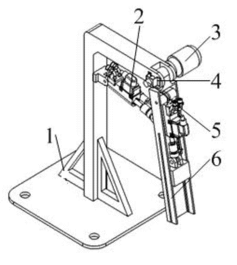
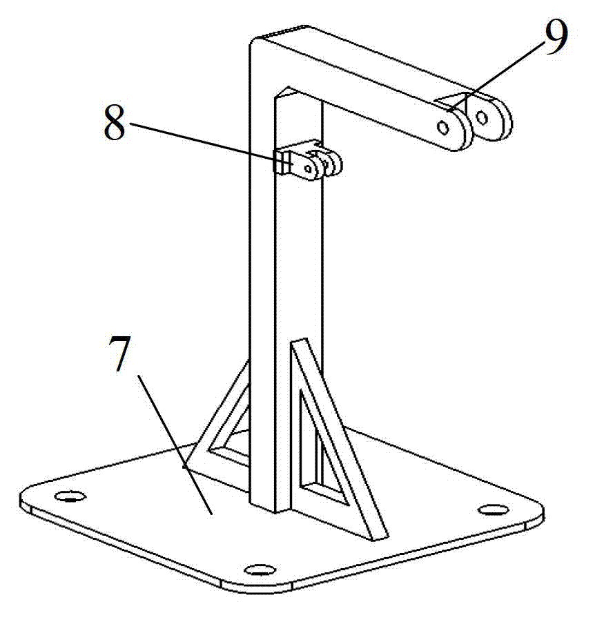
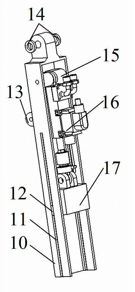
[0022] Such as figure 1 , 2 As shown, a robot single joint fluid pressure and position control test platform includes a cantilever support 1, a first hydraulic servo drive unit 2, a torque motor and a supporting controller 3, an angular displacement sensor bracket 4, and an angular displacement sensor 5. A swing unit 6, a number of sleeves 14 with the same inner diameter and different lengths, the torque motor comes with a flange, the cantilever support 1 includes a cantilever support base 7, a cantilever support lug 8, and a cantilever end 9 . Such as Figure 4 As shown, the hydraulic servo drive unit includes a hydraulic cylinder 22, a piston rod 19, an electro-hydraulic servo valve 21, a linear displacement sensor 20, and a force sensor 18.

[0023] Such as image 3 As shown, the swing unit 6 includes a swing rod 10 (the two walls of the swing rod are provided with sw...


PUM


Abstract

The invention discloses a robot single joint hydraulic pressure and position control test platform which comprises a cantilever bracket, a first hydraulic servo drive unit, a torque motor and a matching controller, an angular displacement sensor bracket, an angular displacement sensor, a swing unit and multiple sleeves, wherein a base of the cantilever bracket is fixed on the ground; the angular displacement sensor bracket, the torque motor and the matching controller are fixed at the cantilever end of the cantilever bracket; the angular displacement sensor is fixed on the angular displacement sensor bracket and connected with an output shaft of the torque motor; the swing unit and the sleeves are connected in series on the output shaft of the torque motor; and one end of the first hydraulic servo drive unit is connected with a support lug of the cantilever bracket, and the other end is connected with the swing unit. With a simple, stable and reliable structure, the robot single joint hydraulic pressure and position control test platform disclosed by the invention can simulate the joint rotary inertia of a robot operation arm in different positions and form displacement tracking closed-loop and force control closed-loop motion, simulates the robot joint control function and verifies the control strategy.

Description

Technical field [0001] The invention relates to a hydraulic pressure and position control test platform, in particular to a robot single joint fluid pressure and position control test platform. Background technique [0002] The robot system is a multi-variable, redundant and nonlinear complex dynamic coupling system. It is composed of multiple joints and multiple links. It has multiple inputs and multiple outputs, and has serious nonlinearity. Robot control development and testing are mostly software simulation. Computer software simulation requires the establishment of robot kinematics and dynamics models, and requires experimental verification. The control development and testing cycle is long and the cost is high. The bench test method overcomes the shortcomings of computer software simulation to a large extent, and has broad application prospects in the development and research of robot control. The force and range of motion of the robot joints are the basis of the mecha...

Claims


Application Information

Patent Timeline
Patent Type & Authority Applications(China)
IPC IPC(8): G05B23/02
Inventor 李贻斌王海燕阮久宏荣学文
Owner SHANDONG UNIV
Why Eureka
Eureka Blog
Learn More