Sectional-type flue gas purifying treatment and waste heat recovery system device, and using method thereof

A waste heat recovery system and flue gas purification technology, applied in separation methods, chemical instruments and methods, combined devices, etc., can solve the problems of single function, resource consumption, complex structure, etc., reduce manufacturing, improve purification efficiency, and simple structure. Effect

Inactive Publication Date: 2012-12-26
TIANJIN WANBO WEIYE TECH DEV
View PDF19 Cites 5 Cited by
  • Summary
  • Abstract
  • Description
  • Claims
  • Application Information

AI Technical Summary

Problems solved by technology

[0012] The above literature provides some methods for flue gas cleaning, but there are complex structures, which cannot be flexibly co

Method used


Image

  • Sectional-type flue gas purifying treatment and waste heat recovery system device, and using method thereof
  • Sectional-type flue gas purifying treatment and waste heat recovery system device, and using method thereof

Examples


Example Embodiment

[0064] Example 1:

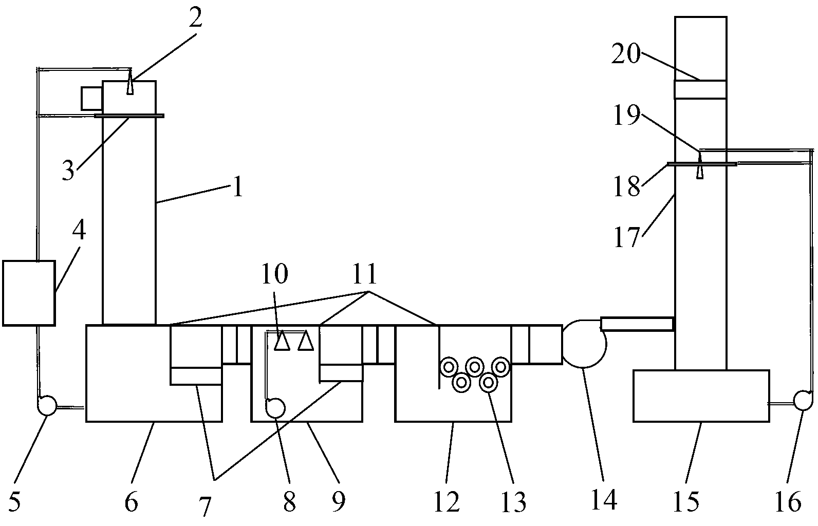
[0065] The segmented flue gas purification treatment and waste heat recovery system device of the present invention is as follows: figure 1 As shown: the system device includes a recovery tower 1, and the air outlet at the lower end of the recovery tower 1 is connected with the air inlet at the top of the recovery water tank 6; the top of the recovery tower 1 is provided with a first liquid atomizing nozzle 2, and the lower part of the air inlet of the recovery tower 1 is provided with a first liquid atomizing nozzle 2. A water film device 3; the lower part of the recovery water tank 6 is connected to the heat exchanger 4 through the first water pump 5, and the heat exchanger 4 is connected to the first liquid atomizing nozzle 2 of the recovery tower 1 and the first water film device 3 through pipelines; recovery The air outlet of the water tank 6 is connected with the air inlet of the multi-stage spray gas cabinet 9, the air outlet of the spray gas cabinet...

Example Embodiment

[0071] Embodiment 2:

[0072] Different from the first embodiment, the spray gas cabinet 9 is directly connected to the discharge tower 17 through the induced draft fan 14, and the photolysis gas cabinet 12 is not provided in the system. Only step 1, step 2, and step 4 of the first embodiment are implemented, and step 3 is not involved.

Example Embodiment

[0073] Embodiment three:

[0074] Different from the first embodiment, the recovery water tank 6 is directly connected to the photolysis gas cabinet 12 , and the system does not have a spray gas cabinet 9 . Only step 1, step 3 and step 4 of the first embodiment are implemented, and step 2 is not involved.


PUM


Abstract

The invention provides a sectional-type flue gas purifying treatment and waste heat recovery system device and a using method of the system device. A recovering tower, a spraying gas tank, a photolysis gas tank and a discharging tower in the system device are flexibly combined according to the components of the flue gas to be treated, different medicals are allocated or photolysis and oxidization techniques are adopted to treat so as to completely clean the flue gas with complex components, purify dust particles and toxic and harmful gas such as sulfur dioxide and hydrogen sulfide, and synchronously recover waste heat of flue gas and steam, in this way, the environment protection object of flue gas clean emission is reached. The sectional-type flue gas purifying treatment and waste heat recovery system device has the following beneficial effects that the flue gas is subjected to dust particle cleaning and waste heat recovering and then is subjected to multiple chemicals sectional reaction and absorption, and multi-stage photolysis and oxidizations so as to treat the toxic and harmful gas in the flue gas, finally the qualified gas is exhausted in air. The system device is suitable for the flue gas generated in industrial incinerations and industrial drying treatments, and is further suitable for the flue gas generated in incinerations of garbage and other substances.

Description

technical field [0001] The invention relates to the treatment of flue gas produced during industrial incineration and drying treatment and a waste heat recovery system device, in particular to a segmented flue gas purification treatment and waste heat recovery system device and its use method. Background technique [0002] At present, the control of flue gas emission is becoming more and more strict at home and abroad. Especially the flue gas produced during industrial furnace incineration, garbage incineration, sludge drying and incineration contains not only dust particles and water vapor, but also sulfur dioxide, nitrogen oxides, hydrogen sulfide, methyl mercaptan, methyl sulfide, dimethyl disulfide Various toxic and harmful gases such as sulfide, ammonia, and styrene must undergo strict purification before they can be discharged into the atmosphere. The national standard GB16297-1996 "Comprehensive Emission Standard of Air Pollutants" and GB14554-93 "Emission Standard o...

Claims


Application Information

Patent Timeline
IPC IPC(8): B01D53/75B01D50/00
Inventor 张宏伟
Owner TIANJIN WANBO WEIYE TECH DEV
Why Eureka
Try Eureka