Compound gas flow generation device under mutual action of atmosphere turbulence and laser

A technology of airflow generation and composite airflow, which is applied in the direction of measuring devices, aerodynamic tests, and testing of machine/structural components. It can solve problems such as thermal and cold deformation of the optical system, installation inside the device, and experimental errors. Achieve the effects of easy motor control, overcoming cost, and fast response

Inactive Publication Date: 2012-12-26
TAIYUAN UNIVERSITY OF SCIENCE AND TECHNOLOGY
View PDF7 Cites 14 Cited by
  • Summary
  • Abstract
  • Description
  • Claims
  • Application Information

AI Technical Summary

Problems solved by technology

However, for the study of the interaction between laser and atmospheric molecules, the factors that must be considered are: (1) different turbulence, such as advection, convection, and turbulence; (2) the realization of multiple optical paths, because the actual laser communication, when When the distance is short, the impression of atmospheric turbulence on the laser is small. When performing long-distance experiments, this patent requires as many single-section simulation devices as possible to be cascaded. Each section is 1m. If you want to reach 100m, you need 100 sections. It is more difficult to realize, and when cascading, it will also cause experimental errors due to multiple passes through the optical window; (3) heating, cooling, and fan lights are installed inside the device, which can easily cause heat loss in the optical system. And cold deformation and vibration will also cause experimental errors

Method used


Image

  • Compound gas flow generation device under mutual action of atmosphere turbulence and laser
  • Compound gas flow generation device under mutual action of atmosphere turbulence and laser
  • Compound gas flow generation device under mutual action of atmosphere turbulence and laser

Examples


Embodiment Construction

[0030] The specific embodiments of the present invention will be described in further detail below in conjunction with the drawings and embodiments. The following examples are used to illustrate the present invention, but not to limit the scope of the present invention.

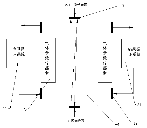
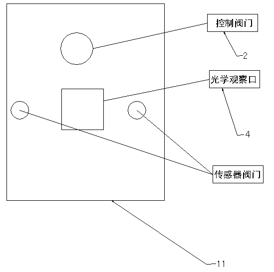
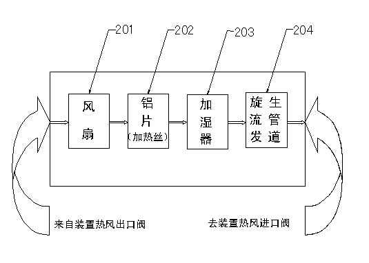
[0031] Such as figure 1 — Figure 5 As shown, a composite air flow generating device interacting with atmospheric turbulence and laser includes air flow generating device main body 1, turbulent circulation system, air inlet, multi-optical path system 3, optical observation window 4, gas parameter sensor 5 and DSP control 器6.

[0032] The main body 1 of the airflow generating device is a cuboid steel structure. The thickness of the steel plate is above 3mm. The main body 1 of the airflow generating device includes an upper cover 11 that can be opened. The upper cover 11 is sealed with rubber sealing around it, and connected by multiple bolts. The distance between them is within 6mm, and the roughness of the contac...


PUM


Abstract

The invention discloses a compound gas flow generation device and in particular relates to a compound gas flow generation device under mutual action of atmosphere turbulence and laser. The compound gas flow generation device comprises a gas flow generation device main body, a turbulence circulation system, a gas inlet, a multi-light-path system, an optical observation window, a gas parameter sensor and a digital signal processing (DSP) controller. The compound gas flow generation device has multiple turbulence modes, so that gases which are different in gas pressure and components can be simulated, and advection and convection can be simulated; an external cold air and hot air circulation system is adopted, so that the system is relatively high in temperature stability and controllability; furthermore, different air fields are produced through different rotational flow guide devices in the circulation controller, so that a relatively complicated atmosphere turbulence environment can be simulated; an improvement-based Harriet multi-light-path system is adopted, so only one compound gas flow device is needed; when the reflection frequency is more than 500, a light path is more than 500 meters; and the problems of high cost, complexity in use and the like which are caused by cascade are solved.

Description

Technical field [0001] The invention relates to a composite air flow generating device, in particular to a composite air generating device in which atmospheric turbulence interacts with a laser. Background technique [0002] The transmission of laser in the atmosphere is closely related to the applications of laser communication, optical radar, satellite remote sensing, remote measurement, laser weapons, etc., due to the high intensity, high coherence, high monochromaticity and high directivity of the laser itself. Characteristics, which have the advantages of large capacity, narrow beam, fast speed, good confidentiality and strong anti-interference, so laser has become the most ideal carrier in wireless optical communication. However, laser transmission in the atmosphere is a very complicated random process. Due to the random fluctuation of atmospheric refractive index, after a certain distance of laser transmission in atmospheric turbulence, the beam will expand, the light inte...

Claims


Application Information

Patent Timeline
Patent Type & Authority Applications(China)
IPC IPC(8): G01M9/08
Inventor 魏计林李旭峰邱选兵李晋红李坤李传亮
Owner TAIYUAN UNIVERSITY OF SCIENCE AND TECHNOLOGY
Why Eureka
Try Eureka