Mixed type underwater navigation detector

A technology for underwater navigation and detectors, which is applied to underwater ships, underwater operating equipment, ships, etc. It can solve the problem of limiting the continuous working ability and application range of aircraft, increasing the risk of aircraft loss, and not being able to automatically recharge and battery life, etc. problem, to achieve the effect of increasing continuous working capacity, simple structure and compact structure

Inactive Publication Date: 2013-01-09
ZHEJIANG UNIV
View PDF7 Cites 59 Cited by
  • Summary
  • Abstract
  • Description
  • Claims
  • Application Information

AI Technical Summary

Problems solved by technology

[0004] 1. It is powered by its own battery, and the data transmission is carried out when the aircraft is floating on the water (or the data is obtained after the aircraft is recovered). It cannot be automatically charged for battery life, and it cannot perform two-way data transmission with the submarine observation network underwater. The continuous working ability and application range of the aircraft
[0005] 2. The propeller propeller and the tail rudder need dynamic seals. In the prior art, the dynamic seals are usually designed in the main seal chamber. Once the dynamic seal fails, water will directly enter the main seal chamber and cause the failure of the main control system, thereby increasing the loss of the aircraft. Danger
[0007] 4. The buoyancy adjustment system mostly adopts the hydraulic method, the system is more complicated, the weight is increased, and the installation and debugging are inconvenient

Method used


Image

  • Mixed type underwater navigation detector
  • Mixed type underwater navigation detector
  • Mixed type underwater navigation detector

Examples


Embodiment Construction

[0024] Further illustrate the present invention below in conjunction with accompanying drawing.

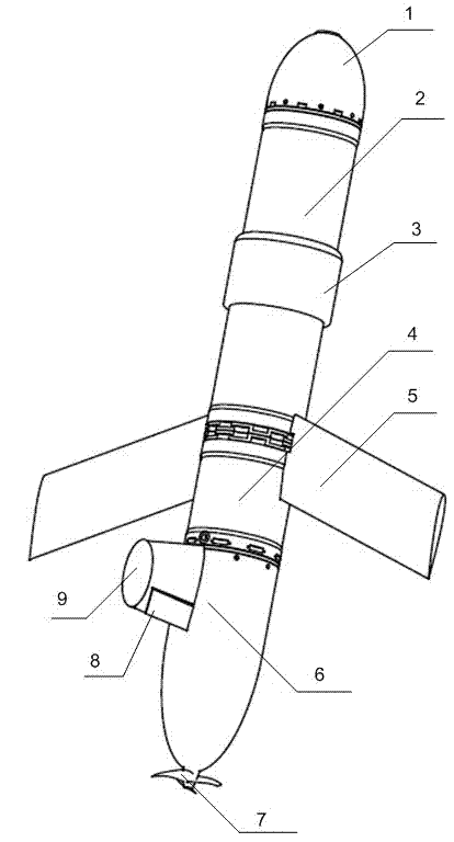
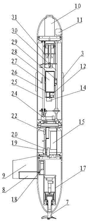
[0025] refer to figure 1 , figure 2 , image 3 with Figure 4 , the hybrid underwater navigation detector of the present invention comprises a fore cabin 1, a main cabin 2, an electronic control cabin 4 and a stern cabin 6 connected successively by a coaxial line, the fore cabin 1 and the stern cabin 6 communicate with the external waters, and the main cabin 2 and the electronic control cabin 4 are airtight cabins; a sonar altimeter 11 and an acoustic transceiver 10 are housed in the bow cabin 1;

[0026] The main cabin 2 is covered with a non-contact power and signal transmission component 3, and the non-contact power and signal transmission component 3 is equipped with an electromagnetic coupling coil, and is filled with insulating oil to achieve a balanced internal and external pressure seal; in the hybrid underwater vehicle and After the underwater connection platform is ...


PUM


Abstract

The invention discloses a mixed type underwater navigation detector which comprises a bow compartment, a main chamber, an electronic control chamber and a peak tank which are coaxially and sequentially connected, wherein the bow compartment and the peak tank are communicated with an outside water area; the main chamber and the electronic control chamber are sealing chambers; two wings are symmetrically installed at a connection position of the main chamber and the electronic control chamber; a sonar height gauge and an acoustic transceiver are installed in the bow compartment; a non-contact electric energy and signal transmission assembly is sleeved outside the main chamber; a gesture adjustment system and a buoyancy adjustment system are installed in the main chamber; the buoyancy adjustment system is installed on the front portion of the main chamber; buoyancy is adjusted through movement of a piston; two sides of the piston are isolated and sealed through rolling membranes; electronic equipment for controlling an aircraft is installed in the electronic control chamber; and a propeller propelling system and a steering control system are fixed on the peak tank. The mixed type underwater navigation detector has characteristics of underwater gliders and autonomous underwater vehicles, and can be abutted with an underwater connection platform to conduct non-contact charging and data transmission, so that continuous operational capability and applied range of underwater aircrafts can be increased.

Description

technical field [0001] The invention relates to an underwater navigation detector for ocean observation, in particular to a hybrid underwater navigation detector combining the characteristics of an underwater glider and an underwater autonomous vehicle. Background technique [0002] At present, the underwater vehicles used for ocean autonomous observation mainly include underwater autonomous vehicles (AUVs) and underwater gliders (Underwater Gliders). Underwater autonomous vehicles are usually driven by propellers. They have the characteristics of strong autonomy and high positioning accuracy, and can detect within a certain range of waters. However, they usually have limited endurance and cannot perform long-term and large-scale detection. Underwater glider is driven by buoyancy, and has the characteristics of long voyage, long cruising time, good concealment, and vertical and vertical plane sampling, but its navigation speed is slow, its autonomy is poor, and it is difficu...

Claims


Application Information

Patent Timeline
Patent Type & Authority Applications(China)
IPC IPC(8): B63G8/14
Inventor 杨灿军彭时林黎开虎毕千谢钰史剑光陈鹰
Owner ZHEJIANG UNIV
Why Eureka
Try Eureka