Flow energy storage battery structure
A battery and electrode technology, which is applied in the direction of fuel cells, regenerative fuel cells, fuel cell components, etc., can solve the problems of limited improvement in voltage efficiency and energy efficiency, and improve energy efficiency and voltage efficiency, and reduce body resistance , reducing the effect of ohmic polarization
- Summary
- Abstract
- Description
- Claims
- Application Information
AI Technical Summary
Problems solved by technology
Method used
Image
Examples
Embodiment 1
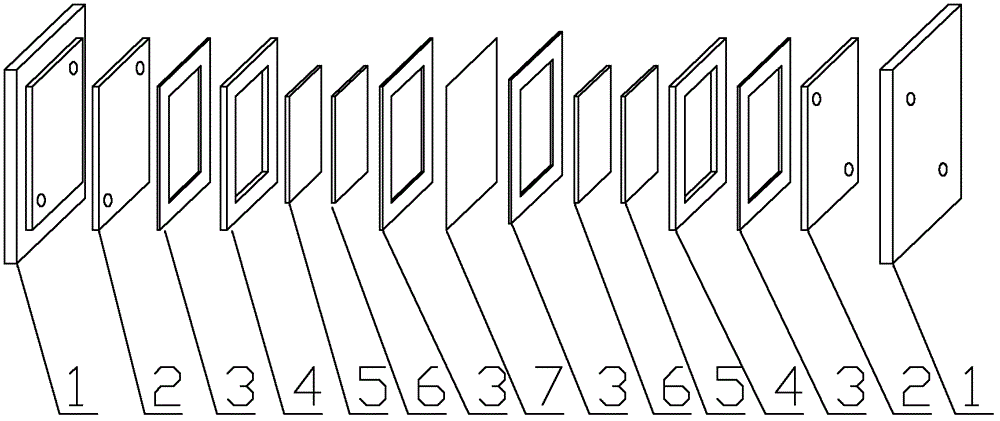
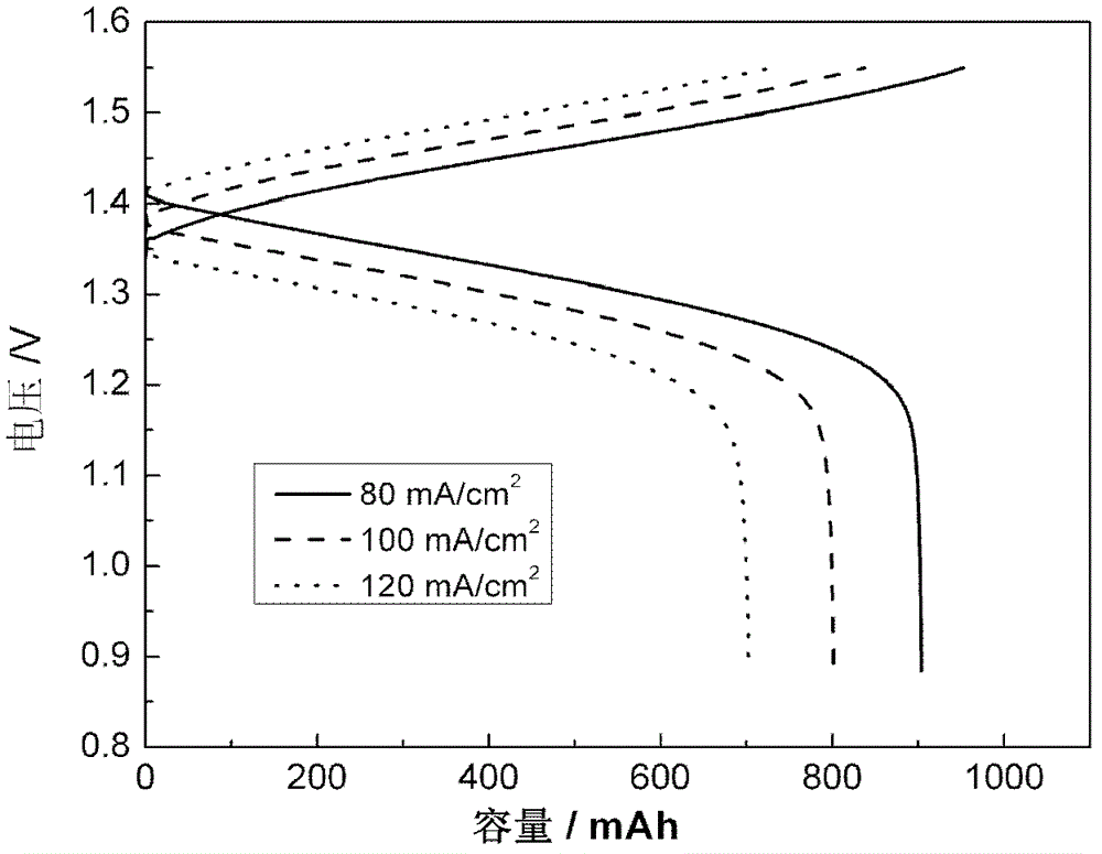
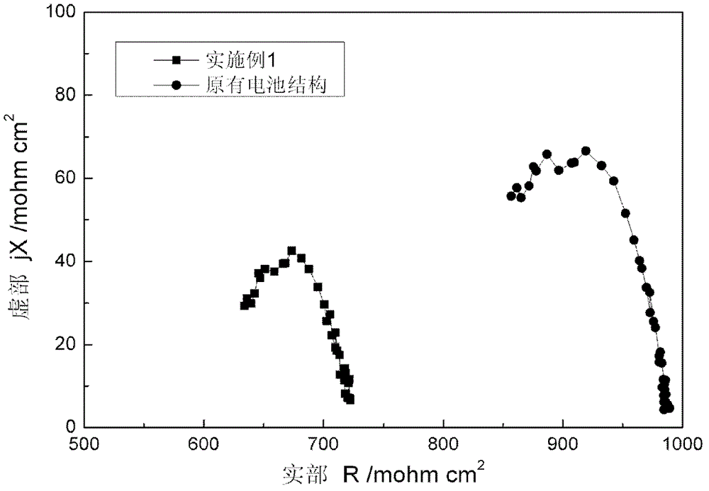
[0030] according to figure 1 The structure shown is assembled into an all-vanadium liquid flow energy storage single cell, in which the electrode frame 4 is 3 mm thick, the filler plate 5 uses a 2 mm thick non-porous graphite plate, the electrode 6 is a 3 mm thick carbon felt, and the non-porous graphite plate and carbon felt The area is 12cm 2 , the sealing gasket 3 is 0.5mm thick silicone rubber; the initial positive electrode electrolyte is 1.5M VO 2+ 3M H 2 SO 4 Solution 40ml, the initial negative electrode electrolyte is 1.5M V 3+ 3MH 2 SO 4 Solution 40ml. The battery charge termination voltage is 1.55V, and the discharge termination voltage is 0.9V. The charging and discharging curves and battery efficiency of the battery at different current densities are as follows: figure 2 and shown in Table 1. The single battery adopting the battery structure of the present invention has a current density of 80mA / cm 2 , the voltage efficiency and energy efficiency were 90...
Embodiment 2
[0033] according to figure 1 The structure shown is assembled into an all-vanadium flow energy storage single cell, in which the electrode frame 4 is 3mm thick, and the filling plate 5 uses a 2mm thick flexible graphite plate, and the density of the flexible graphite plate is 1.5g / cm 3 , the porous electrode 6 is a 3mm thick carbon felt, and the area of the flexible graphite plate and the carbon felt is 12cm 2 , the sealing gasket 3 is 0.5mm thick silicone rubber; the initial positive electrode electrolyte is 1.5M VO 2+ 3M H 2 SO 4 Solution 40ml, the initial negative electrode electrolyte is 1.5M V 3+ 3M H 2 SO 4 Solution 40ml. The battery charge termination voltage is 1.55V, and the discharge termination voltage is 0.9V.
[0034] The cell efficiency of the single cell in this embodiment at different current densities is shown in Table 1, and the current density is increased to 120mA / cm 2 , the voltage efficiency and energy efficiency still remain at 84.3% and 81.4%....
Embodiment 3
[0036] according to figure 1 The structure shown is assembled into an all-vanadium liquid flow energy storage single cell, in which the electrode frame 4 is 3 mm thick, and the filling plate 5 uses a 1 mm thick flexible graphite plate, and the density of the flexible graphite plate is 1.5 g / cm 3 , the porous electrode 6 is a 4mm thick carbon felt, and the area of the flexible graphite plate and the carbon felt is 12cm 2 , the sealing gasket 3 is 0.5mm thick silicone rubber; the initial positive electrode electrolyte is 1.5M VO2+ 3M H 2 SO 4 Solution 40ml, the initial negative electrode electrolyte is 1.5M V 3+ 3M H 2 SO 4 Solution 40ml. The battery charge termination voltage is 1.55V, and the discharge termination voltage is 0.9V.
[0037] The cell efficiency of the single cell in this embodiment at different current densities is shown in Table 1, and the current density is increased to 120mA / cm 2 , the voltage efficiency and energy efficiency remained at 82.4% and 79...
PUM
| Property | Measurement | Unit |
|---|---|---|
| density | aaaaa | aaaaa |
Abstract
Description
Claims
Application Information
 - R&D
- Intellectual Property
- Life Sciences
- Materials
- Tech Scout
- Unparalleled Data Quality
- Higher Quality Content
- 60% Fewer Hallucinations
Browse by: Latest US Patents, China's latest patents, Technical Efficacy Thesaurus, Application Domain, Technology Topic, Popular Technical Reports.
© 2025 PatSnap. All rights reserved.Legal|Privacy policy|Modern Slavery Act Transparency Statement|Sitemap|About US| Contact US: help@patsnap.com


