Method for correcting error of polarization detection device

A detection device and polarization technology, which is applied to the measurement device, the polarization of the measurement light, the instrument, etc., can solve the problems of inability to measure the positioning error, the process is cumbersome, and the influence cannot be eliminated, and the effect of avoiding simulation and table lookup is achieved.

Active Publication Date: 2014-05-07
SHANGHAI INST OF OPTICS & FINE MECHANICS CHINESE ACAD OF SCI
View PDF8 Cites 0 Cited by
  • Summary
  • Abstract
  • Description
  • Claims
  • Application Information

AI Technical Summary

Problems solved by technology

However, this method still cannot measure the positioning error in the direction of the fast axis of the phase retarder installed in the polarization detection device and the direction of the light transmission axis of the analyzer, and cannot eliminate the influence of the angular positioning error of the components that constitute the polarization detection device on the measurement.
Prior technology 3 (Chinese patent: 201010268324.5) proposed a method for measuring device errors in polarization detection devices, but this method needs to obtain a theoretical surface through simulation, and then based on the polarization azimuth error and polarization degree error of the two measurements in Find the corresponding error point on the theoretical surface to determine the device error, similar to the method of looking up the table, the process of determining the error is cumbersome

Method used


Image

  • Method for correcting error of polarization detection device
  • Method for correcting error of polarization detection device
  • Method for correcting error of polarization detection device

Examples


Embodiment Construction

[0030] The present invention will be further described below in conjunction with the embodiments and accompanying drawings, but the protection scope of the present invention should not be limited thereby.

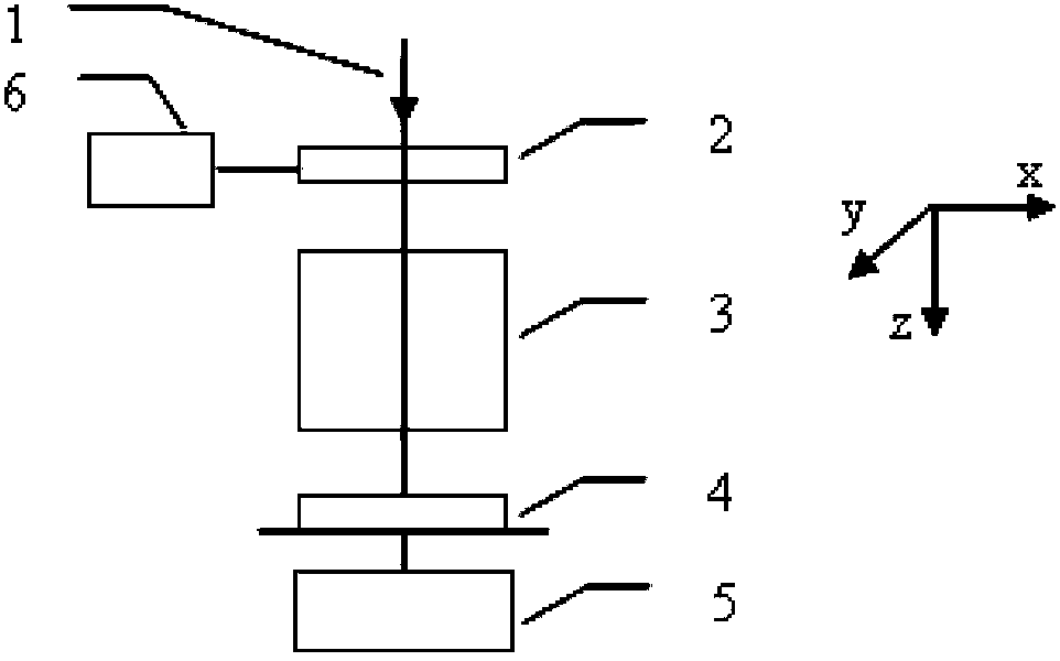
[0031] see first figure 1 , figure 1 It is a schematic diagram of the polarization detection device involved in the correction method of the device error of the polarization detection device of the present invention. Depend on figure 1 It can be seen that the composition of the polarization detection device involved in the present invention includes a phase retarder 2, a polarizer 3 and a photodetector 4 arranged in sequence along the optical axis of the device system, and the output of the photodetector 4 is connected to the signal processing system 5, and the The phase retarder 2 can rotate around the optical axis of the device system under the drive of the driver 6, and the light beam is incident on the phase retarder 2 and the analyzer 3 parallel to the optical axi...


PUM


Abstract

The invention discloses a method for correcting an error of a polarization detection device. The polarization detection device comprises a phase retarder, an analyzer and a photoelectric detector which are sequentially arranged along an optical axis of the device system, wherein the output of the photoelectric detector is connected with a signal processing system; and the linearly polarized light with the Stokes parameter of (1, 1, 0, 0) enters the polarization detection device. The method comprises the following steps of: setting the angle of a transparent shaft of the analyzer to be 0 and performing measurement for the first time to obtain a first measurement error of the normalized Stokes parameter; setting the angle of the transparent shaft of the analyzer to be 45 degrees and performing measurement for the second time to obtain a second measurement error of the normalized Stokes parameter; and solving the phase retardation error of the phase retarder, the fast axis angle error and the transparent shaft angle error of the analyzer in the polarization detection device so as to realize error correction. According to the method, the device error in the polarization detection device can be measured under the condition that the polarization detection device does not need to be detached, so that the device error is corrected.

Description

technical field [0001] The invention relates to a polarization detection device, in particular to a method for correcting device errors of the polarization detection device. Background technique [0002] The progress of semiconductor manufacturing technology is always driven by the reduction of exposure wavelength, the increase of numerical aperture of projection objective lens and the reduction of lithography process factor k1. In recent years, immersion lithography technology has been developed rapidly. In immersion lithography, a certain liquid is used to fill between the last lens of the objective lens and the photoresist on the silicon wafer, so that the numerical aperture of the projection objective lens is significantly improved. When the numerical aperture of the projection objective lens is close to 0.8 or larger, the influence of the polarization state of the illumination light on the lithography imaging can no longer be ignored. Using properly polarized illumina...

Claims


Application Information

Patent Timeline
Patent Type & Authority Patents(China)
IPC IPC(8): G01J4/04
Inventor 李中梁王向朝汤飞龙
Owner SHANGHAI INST OF OPTICS & FINE MECHANICS CHINESE ACAD OF SCI
Why Eureka
Try Eureka