
Method for cutting light emitting diode chip through deep etching

A technology of light-emitting diodes and deep etching, which is applied in the direction of electrical components, circuits, semiconductor devices, etc., can solve the problems of increasing difficulty in the split process, narrow modified layer, and affecting efficiency, so as to reduce split operations, increase light output efficiency, and avoid collapse The effect of edge chipping

Inactive Publication Date: 2013-01-16
施科特光电材料(昆山)有限公司
View PDF0 Cites 16 Cited by
  • Summary
  • Abstract
  • Description
  • Claims
  • Application Information

AI Technical Summary

Problems solved by technology

However, this processing method also has disadvantages: the modified layer in the chip is relatively narrow, which invisibly increases the difficulty of the splitting process. If the laser power is increased to expand the width of the modified layer, it will inevitably affect the life of the laser and is not conducive to mass production
Two times of laser processing will also inevitably affect the efficiency
Stealth cutting equipment is expensive and costly, which is a major disadvantage of stealth cutting technology

Method used


Image

  • Method for cutting light emitting diode chip through deep etching
  • Method for cutting light emitting diode chip through deep etching
  • Method for cutting light emitting diode chip through deep etching

Examples


Embodiment Construction

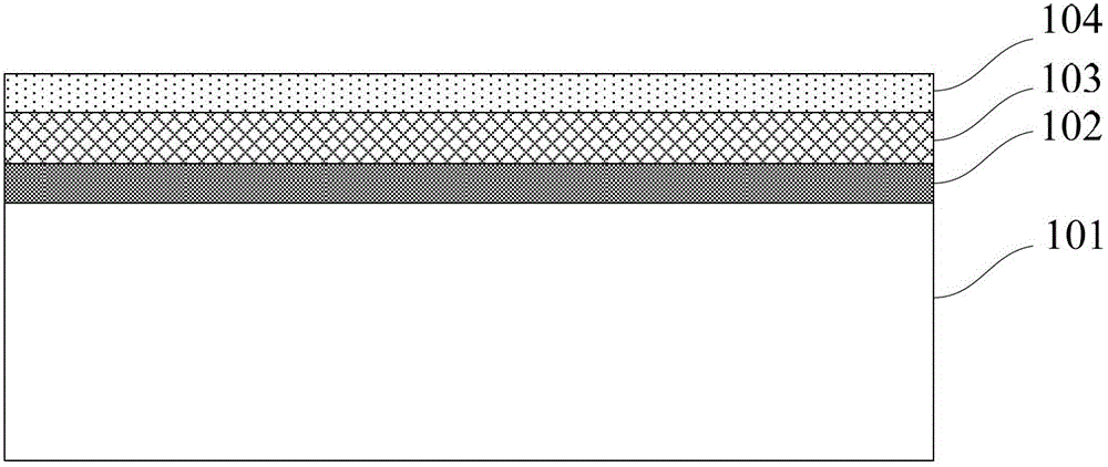
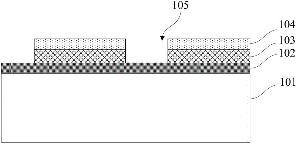
[0054] Embodiments of the present invention are described below through specific examples, and those skilled in the art can easily understand other advantages and effects of the present invention from the content disclosed in this specification. The present invention can also be implemented or applied through other different specific implementation modes, and various modifications or changes can be made to the details in this specification based on different viewpoints and applications without departing from the spirit of the present invention.

[0055] see Figure 1~Figure 13 . It should be noted that the diagrams provided in this embodiment are only schematically illustrating the basic idea of ​​the present invention, and only the components related to the present invention are shown in the diagrams rather than the number, shape and shape of the components in actual implementation. Dimensional drawing, the type, quantity and proportion of each component can be changed arbit...


PUM


Abstract

The invention provides a method for cutting a light emitting diode chip through deep etching. The method comprises the following steps: firstly, forming a light emitting element comprising a plurality of light emitting units on the surface of a semiconductor substrate; then fabricating a protecting layer with etching windows formed at the connections between each of the light emitting units; etching from each of the etching windows to form sliver channels; next, filling each of the sliver channels with insulation material and thinning the semiconductor substrate from back until exposing the insulation material; and finally making a back coating, removing the insulation material in each of the sliver channel, and expanding the film to obtain independent light emitting units. According to the invention, by adopting the method of forming the sliver channels through deep etching, the cut grooves are deep into the sapphire substrate, thus avoiding laser cutting processing step, avoiding the problem of light absorption caused by laser ablation, and increasing light outgoing efficiency; and the deep etching depth is equivalent to the final thickness of the chip, and separated chip grains can be obtained by removing the filled SiO2, thus reducing sliver operation, avoiding broken sides and broken corners in the slivers, and increasing the yield.

Description

technical field [0001] The invention relates to a cutting method of a light emitting diode, in particular to a method for deep etching and cutting a light emitting diode chip. Background technique [0002] GaN-based light-emitting diodes (Light Emitting Diode, abbreviated as LED) have the advantages of high efficiency, energy saving, environmental protection, and long service life, and are widely used in the fields of image display, signal indication, and lighting. In recent years, driven by new technologies, GaN-based light-emitting diode-related research and manufacturing fields have developed rapidly. However, its low luminous efficiency has always restricted its application in the lighting industry and is also the main reason for its replacement of traditional lighting. bottleneck. To improve its brightness, in addition to factors in epitaxial growth, the cutting method in chip manufacturing will also have a certain impact on brightness. At present, the cutting methods...

Claims


Application Information

Patent Timeline
Patent Type & Authority Applications(China)
IPC IPC(8): H01L33/00H01L21/78
Inventor 杨旅云陈晓鹏张宇欣张国龙吴东平常志伟薛进营王明辉夏成
Owner 施科特光电材料(昆山)有限公司
Learn More