
CO (carbon monoxide) full-radial isothermal converting furnace

A technology of isothermal transformation and furnace body, which is applied in the field of temperature transformation furnace, can solve the problems of reactor overtemperature, isothermal reactor overtemperature, complex structure, etc., and achieve the effect of uniform gas distribution, small bed resistance and large flow area

Active Publication Date: 2013-01-23
CHINA PETROCHEMICAL CORP +2
View PDF4 Cites 15 Cited by
  • Summary
  • Abstract
  • Description
  • Claims
  • Application Information

AI Technical Summary

Problems solved by technology

[0004] The Chinese patent with the notification number CN101721956A applied for an "Isothermal Low-Temperature CO Shift Reactor". In this isothermal reactor, the boiler water used to remove the heat of reaction enters from the top of the heat exchange pipe, and the steam generated is also from the top of the heat exchange pipe. Removed in the form of self-evaporation, which makes the fluidity of the boiler water very poor, the ability to remove the heat of reaction through the boiler water is limited, and the reactor still has the risk of overheating
[0005] The isothermal reactor superheats the saturated medium-pressure steam produced by itself. This design scheme is difficult to implement in the engineering process because the specific heat of the saturated medium-pressure steam is very small. In the isothermal reactor, the saturated medium-pressure In the process of steam turning into superheated medium-pressure steam, the heat absorbed is very little, and the transformation reaction heat cannot be effectively removed, which will definitely cause local overheating of the isothermal reactor and burn out the transformation catalyst at the local overtemperature
[0006] The isothermal reactor adopts a fully enclosed type, and the catalyst can only be loaded during the equipment manufacturing process. The loading, unloading and replacement of the catalyst after deactivation cannot be realized. In addition, if the heat exchange tube is broken, it cannot be repaired or blocked.
[0007] The interior of the isothermal reactor is divided into a steam chamber and a water chamber, and the lower part has a heat exchange tube and an inverted U-shaped tube. The structure is complex, the manufacturing process is difficult, and the cost is high.
[0008] The CO conversion reaction in the isothermal reactor occurs above 250°C. The upper and lower parts of the inner cylinder where the heat exchange tube bundle is located are welded to the outer cylinder of the reactor. The thermal stress in the furnace cannot be released at high temperature, which will cause the inner cylinder to bend and deform.

Method used


Image

  • CO (carbon monoxide) full-radial isothermal converting furnace
  • CO (carbon monoxide) full-radial isothermal converting furnace
  • CO (carbon monoxide) full-radial isothermal converting furnace

Examples


Embodiment 1

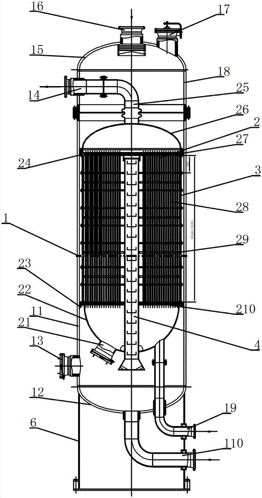
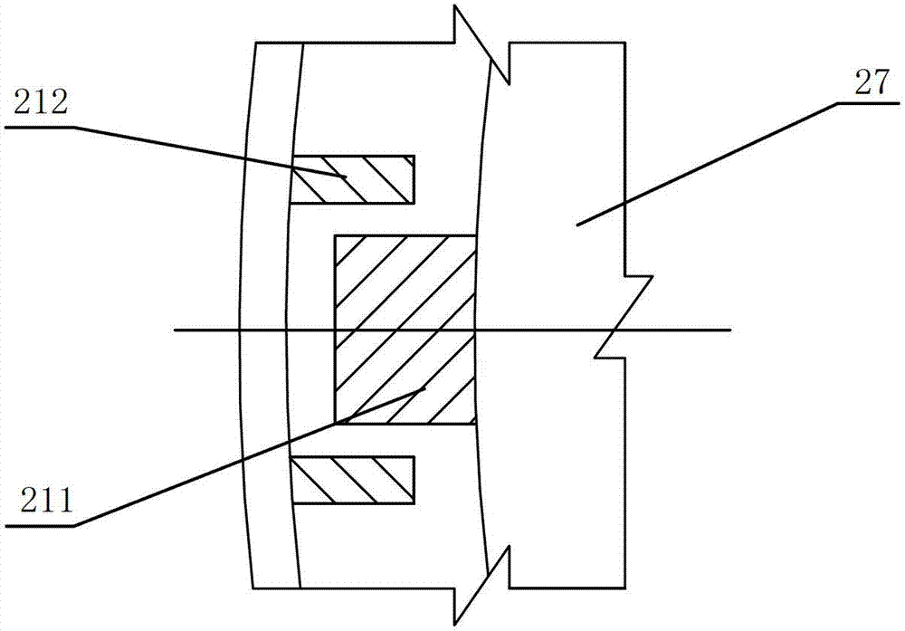
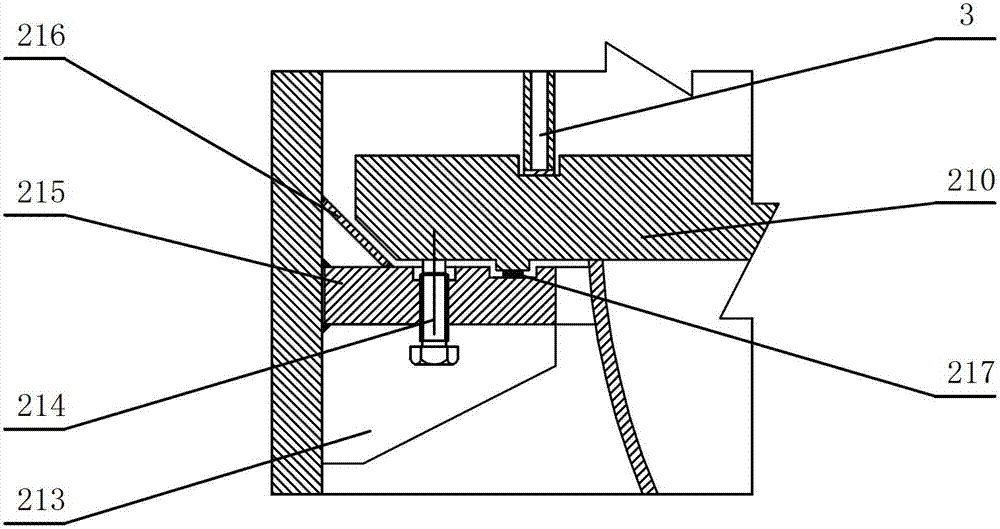
[0040] Figure 1 to Image 6 As shown, the CO omni-radial isothermal shift furnace includes:

[0041] The furnace body 1 includes a main body 11, an upper head 15 and a lower head 12, a transition section 18 is provided between the main body 11 and the upper head 15, and a flange is detachably connected between the main body 11 and the transition section 18. The main body 11 It is welded with the lower head 12, the upper head 15 and the transition section 18. The top of the upper head 15 is provided with a reaction gas inlet 16 and an upper maintenance manhole 17, a circulating cooling water outlet 14 is provided on the side wall of the transition section 18, a lower maintenance manhole 13 is provided on the side wall of the lower end of the main body 11, and a lower maintenance manhole 13 is provided at the bottom of the lower head. There is a cooling water inlet 19 and a shift gas outlet 110. The bottom of the furnace body 1 is seated on the skirt 6, which is the supporting ...

Embodiment 2

[0046] Such as Figure 7 , Figure 8 As shown: the gas distributor in the CO omni-radial isothermal shift furnace is composed of several distributors with the same structure bolted together, each distributor includes an inner cylinder 55 and an outer cylinder 54, and the inner cylinder 55 consists of a triangular shape with a length of 500mm The ribs are arranged in gaps. The outer cylinder 54 is composed of two semicircular cylinders. Two sets of vertical connecting plates 53 are welded at both ends of the semicircular outer cylinder to bolt the semicircular cylinders together to form a cylindrical cylinder. The outer cylinder 54 is uniformly distributed with round holes, and the inner cylinder 55 is used as a gas secondary distributor. The gap between the triangular ribs is smaller than the diameter of the outer cylinder and not greater than 3mm. At the same time, the contact between the outer cylinder and the upper tube plate 27 is kept at a height of 100mm without opening ...


PUM

PropertyMeasurementUnit
Lengthaaaaaaaaaa

Abstract

The invention relates to a CO (carbon monoxide) full-radial isothermal converting furnace comprising a furnace body, a heat-exchanging pipe bundle and a gas collector and being characterized in that the furnace body comprises a first segment of furnace body at the upper part and a second segment of furnace body at the lower part, which are detachably connected, a gas distributor is arranged in the second segment of furnace body; the upper end and the lower end of the gas distributor are respectively connected with an upper pipe plate and a lower pipe plate; an upper seal is arranged above the upper pipe plate while a lower seal is arranged below the lower pipe plate; and the heat-exchanging pipe bundle is arranged in the gas distributor. Compared with the prior art, the CO full-radial isothermal converting furnace provided by the invention has the advantage that a series of problems such as long process, multiple reaction stages, high system pressure reduction, high equipment investment, likely-occurred temperature exceeding of the converting furnace, short catalyst life, and the like in a high water-gas ratio CO conversion technique in the prior art are solved.

Description

technical field [0001] The invention relates to the field of chemical equipment, in particular to a CO omni-radial isothermal shift furnace. Background technique [0002] At present, in the design process of high-concentration CO shift process generated by pulverized coal gasification in China, the shift furnace adopts adiabatic reactor. Due to the high content of CO in the crude synthesis gas and the shift reaction is a strong exothermic process, the transformation unit adopts multiple adiabatic furnaces connected in series to carry out the CO shift reaction, and the reaction heat is removed between the furnaces. This has also caused the traditional high-concentration CO shift process to be complex, with a large number of reactors, large system pressure drop, high equipment investment, and difficult temperature control of the shift furnace. It is easy to overheat during catalyst vulcanization and normal operation, posing safety hazards; adiabatic temperature rise A series ...

Claims


Application Information

Patent Timeline
IPC IPC(8): B01J8/02C01B3/16
Inventor 许仁春施程亮张唯玮涂林陆亚东刘锋
Owner CHINA PETROCHEMICAL CORP
Learn More