Polarization-maintaining photonic crystal fiber and panda fiber welding method

A photonic crystal fiber, panda fiber technology, applied in the direction of coupling of optical waveguides, can solve the problems of unsuitable application of ordinary photonic crystal fibers, high hardware and operation requirements, difficult polarization axis alignment, etc. Shaft accuracy and the effect of improving weld strength

Inactive Publication Date: 2013-01-23
BEIHANG UNIV
View PDF1 Cites 15 Cited by
  • Summary
  • Abstract
  • Description
  • Claims
  • Application Information

AI Technical Summary

Problems solved by technology

[0011] This technology requires the use of expensive laser fusion splicing equipment. Although reasonable parameter optimization can achieve a good splicing effect, the splicing process is very complicated and requires high hardware and operation, which is not suitable for ordinary photonic crystal fiber applications.
The most important thing is that this technology is difficult to achieve the alignment of the polarization axis

Method used


Image

  • Polarization-maintaining photonic crystal fiber and panda fiber welding method
  • Polarization-maintaining photonic crystal fiber and panda fiber welding method
  • Polarization-maintaining photonic crystal fiber and panda fiber welding method

Examples


Embodiment Construction

[0042] The present invention will be further described in detail below in conjunction with the accompanying drawings and embodiments.

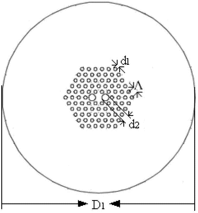
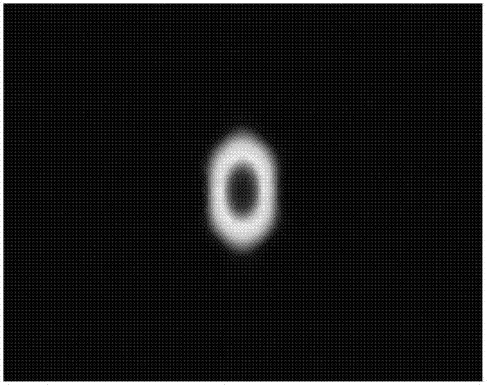
[0043] Polarization-maintaining photonic crystal fiber (YOFC) such as Figure 1a As shown, its microstructure consists of air holes arranged in a hexagon on the outside and two large holes symmetrically distributed close to the core. D 1 is the outer diameter of the fiber (D in this example 1 = 125 μm), d 1 is the hole diameter (d in this example 1 = 2.2 μm), d 2 is the diameter of the large hole (d in this example 2 =4.5μm), Λ is the hole spacing (Λ=4.4μm in this example). By simulating and measuring the mode field of polarization-maintaining photonic crystal fibers, such as Figure 2a and Figure 2b As shown, the mode field of the polarization-maintaining photonic crystal fiber is 2.8 μm / 4.6 μm and the principal axes of polarization (fast axis and slow axis) are obtained.

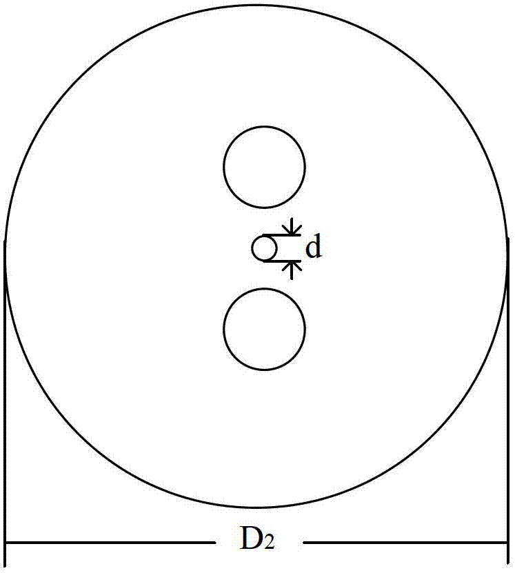
[0044] Panda Fiber (YOFC) such as Figure 1b As shown, from...


PUM


Abstract

The invention discloses a polarization-maintaining photonic crystal fiber and panda fiber welding method. The polarization-maintaining photonic crystal fiber and panda fiber welding method is characterized by comprising a step 1 of selecting an initial position of a fiber, a step 2 of aligning a polarization shaft, and a step 3 of welding. The polarization-maintaining photonic crystal fiber and panda fiber welding method realizes better matching of two fiber mode fields and lowering welding consumption by controlling collapse of an air hole of a photonic crystal fiber and a diameter at the welding point of the panda fiber. The polarization-maintaining photonic crystal fiber and panda fiber welding method lowers welding consumption and improves welding intensity by adding a propelling distance in a fiber welding process appropriately. By adopting a novel welding machine and an end face imaging and shaft alignment technology, the polarization-maintaining photonic crystal fiber and panda fiber welding method can realize alignment of the polarization shafts of both the photonic crystal fiber and the panda fiber and improve shaft alignment precision. The polarization-maintaining photonic crystal fiber and panda fiber welding method, disclosed by the invention, has the advantages of being simple in technology, only needing once welding, and being easy to operate, good in repeatability and applicable for welding between photonic crystal fibers of the other types and traditional single-mode fibers.

Description

technical field [0001] The invention relates to a fusion splicing method of a polarization-maintaining photonic crystal optical fiber and a panda optical fiber, which is applied to the field of photonic crystal optical fiber gyro and other photonic crystal optical fiber sensing technologies. Background technique [0002] The polarization-maintaining photonic crystal fiber introduces two large air holes in the periodic structure of the cladding to achieve high birefringence, thereby achieving the function of maintaining polarization. Due to its new structure and light guiding mechanism, it has many different characteristics from traditional polarization-maintaining fibers, which are very beneficial to the application of fiber optic gyroscopes, as follows: [0003] (1) Low bending loss, the minimum bending diameter can reach 2mm, no loss, which is helpful for the miniaturized design of the gyroscope. [0004] (2) Pure silica material, no doping, strong radiation resistance. ...

Claims


Application Information

Patent Timeline
Patent Type & Authority Applications(China)
IPC IPC(8): G02B6/255
Inventor 宋镜明孙祚明宋凝芳刘海霞徐宏杰王曙
Owner BEIHANG UNIV
Why Eureka
Try Eureka