Treatment system and treatment method for removing hydrogen sulfide from acid gas

A sour gas and treatment system technology, applied in chemical instruments and methods, separation methods, chemical recovery, etc., can solve problems such as inability to be measured, small operating flexibility, and affecting system operation, so as to save investment and construction period, and achieve good operation The effect of flexibility and simplified equipment structure

Active Publication Date: 2013-01-30
美景(北京)环保科技有限公司
View PDF3 Cites 50 Cited by
  • Summary
  • Abstract
  • Description
  • Claims
  • Application Information

AI Technical Summary

Problems solved by technology

[0022] 1. The equipment structure is complicated, the investment is high, and the design and construction period is long;
[0023] 2. The circulation rate of the solution is set by the initial geometry of the self-circulating reactor, which can neither be measured nor controlled during operation;
[0024] 3. Although the self-circulation process can operate under 0~100% load in theory, since the self-circulation system needs to use the promotion of acid gas and air to realize the circulation of the solution in the reactor, when the amount of acid gas is low or due to sulfidation When the hydrogen load is low and the required air volume is low, the solution cannot form self-circulation and the system cannot operate
However, if the high air volume continues to be maintained at this time, it will lead to excessive oxidation of the catalyst and hydrogen sulfide, which will also affect the operation of the system, so the operating flexibility in practical applications is much smaller
Can not give full play to the advantages of high flexibility in the operation of complex iron hydrogen sulfide removal process

Method used


Image

  • Treatment system and treatment method for removing hydrogen sulfide from acid gas
  • Treatment system and treatment method for removing hydrogen sulfide from acid gas

Examples


Embodiment Construction

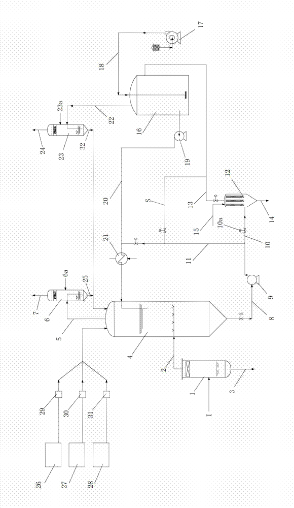
[0049] figure 1 It is a schematic diagram of an acid gas removal hydrogen sulfide treatment system according to an embodiment of the present invention. Such as figure 1 As shown, in an embodiment of the present invention, the acid gas removal hydrogen sulfide treatment system includes a waste gas pretreatment unit, an absorption reaction unit, a sulfur filtration unit, a solution regeneration unit, a temperature control unit, a chemical delivery unit and a tail gas treatment unit.

[0050] The exhaust gas pretreatment unit is used to pretreat the acid gas passed in to remove impurities; the absorption reaction unit has a complex iron catalyst desulfurization solution, which is used to absorb and oxidize hydrogen sulfide in the acid gas passed into it into a simple substance Sulfur; the sulfur filtration unit is used to filter the elemental sulfur formed by oxidation; the solution regeneration unit is used to oxidize and regenerate the complex iron catalyst desulfurization sol...


PUM


Abstract

The invention relates to a treatment system and a treatment method for removing hydrogen sulfide from acid gas. The treatment system comprises an absorption reaction unit, a sulphur filtering unit, a solution regeneration unit, a temperature control unit and a medicament deliver unit, wherein the absorption reaction unit has a ferrum-catalyst desulfuration solution, is used for absorbing hydrogen sulfide contained in the acid gas introduced in the ferrum-catalyst desulfuration solution, and oxidizing the hydrogen sulfide into sulphur; the sulphur filtering unit is used for filtering the sulphur; and the solution regeneration unit is used for oxidizing and regenerating the filtered ferrum-catalyst desulfuration solution. The sulphur filtering unit is positioned between the absorption reaction unit and the solution regeneration unit. According to the system and the method, the sulphur is filtered from the solution before the step of oxidation and regeneration, so that the sulphur can not be deposited at the bottom end of an oxidization regenerator, the concentration of the sulphur in the system is low, so that the system can operate stably for a long time, and has good operational flexibility under various work conditions; the structure of equipment can be simplified; the investment is saved; and the construction period is also saved.

Description

technical field [0001] The invention relates to a gas treatment system and treatment method, in particular to an acid gas removal hydrogen sulfide treatment system and treatment method. Background technique [0002] Hydrogen sulfide is a very harmful impurity in industrial gases such as petrochemical, natural gas, oilfield development, coke oven gas and semi-water gas. Its existence will not only cause corrosion of equipment and pipelines, but also cause serious harm to the environment, and it is a pollutant that must be eliminated or controlled. [0003] In the hydrogen sulfide removal process, the large-scale desulfurization system, such as the system with an elemental sulfur output of more than 5,000 tons per year, generally adopts the CLAUS process; for small-scale desulfurization systems, the following two wet catalytic oxidation processes are most widely used. 1) Complex iron catalyst absorption solution; 2) Metal vanadium catalyst absorption solution. In addition, t...

Claims


Application Information

Patent Timeline
Patent Type & Authority Applications(China)
IPC IPC(8): B01D53/86B01D53/52C01B17/05
CPCY02P20/584
Inventor 胡惊雷
Owner 美景(北京)环保科技有限公司
Why Eureka
Try Eureka