Active cooling process for machine tools

An active cooling, machine tool technology, applied in metal processing machinery parts, maintenance and safety accessories, metal processing equipment, etc., can solve the problems of small heat generation of workpieces and tools, small demand for coolant, energy waste, etc., to achieve energy utilization The effect of high rate, easy implementation and simple technical principle

Inactive Publication Date: 2013-01-30
王萌
View PDF5 Cites 11 Cited by
  • Summary
  • Abstract
  • Description
  • Claims
  • Application Information

AI Technical Summary

Problems solved by technology

On the contrary, when the rotation speed of the tool and the workpiece is low and the feed rate of the tool is small, the heat generated by the workpiece and the tool is small, and the demand for coolant is also

Method used


Image

  • Active cooling process for machine tools

Examples


Embodiment Construction

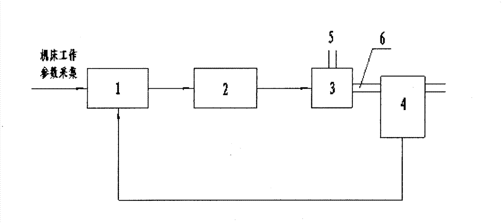
[0017] figure 1 It is a schematic diagram of the principle of the active cooling technology of a machine tool of the present invention. figure 1 , the cooling system of this technology is mainly composed of a controller 1, a frequency converter 2, a pump 3 and a flow monitor 4. The front end of the pump 3 is connected to the frequency converter 2, the frequency converter 2 is connected to the controller 1, and the flow monitor 4 is installed in the pump. 3 exit 6.

[0018] When the machine tool is working, parameters such as the workpiece speed, the actual power of the machine tool spindle or the tool speed and the tool feed amount are automatically extracted or manually input by the controller 1. In this state, the appropriate parameters of the required coolant flow are converted into current or voltage signals and sent to the inverter 2. The inverter 2 adjusts the current input of the pump 3, and then adjusts the speed of the pump 3, thereby adjusting the pump outlet 6 At ...


PUM


Abstract

The invention discloses an active cooling process for machine tools. A cooling system utilizing the active cooling process mainly comprises a controller, a frequency converter, a pump and a flow rate monitor. Parameters such as rotational speed of workpieces, actual power of machine tool spindles, or rotational speed of tools and feed rate during operation of the machine tools are input by the controller in an automatic extracting or by-hand input manner, and by treatment of the cooling system utilizing the active cooling process, supply of cooling liquid can keep dynamically balanced with a running state of the machine tools on the premise of meeting cooling requirements of operations of the machine tools, so that the purpose of reducing energy consumption of the machine tools is achieved. By the active cooling process of the machine tools, the machine tools are cooled effectively, energy utilization rate is increased, and energy saving effect is remarkable.

Description

technical field [0001] The invention belongs to the technical field of machine tool design and manufacture, and in particular relates to an active cooling technology for machine tools that can automatically adjust the flow of cooling liquid when the machine tool is working. Background technique [0002] The cooling system is an important part of the machine tool. The purpose of cooling is to reduce the temperature of the processing area, avoid workpiece burns, improve the processing quality of the workpiece and the durability of the tool (or grinding wheel). [0003] The cooling technology commonly used in existing machine tools is to use a pump to pump the coolant at a constant flow rate directly to the parts of the machining area that need to be cooled. The disadvantage of this cooling technology is that no matter what the working state of the machine tool is, as long as the cooling system of the machine tool is turned on, the pump always runs at a constant power, that is ...

Claims


Application Information

Patent Timeline
IPC IPC(8): B23Q11/10
Inventor 王萌王景华李献会
Owner 王萌
Why Eureka
Try Eureka