Coal tar hydrogenation method
A process method and coal tar technology are applied in the field of prolonging the life of a coal tar hydrogenation catalyst, which can solve problems such as difficult treatment, and achieve the effects of difficult treatment, simple and easy method, and high catalytic activity.
- Summary
- Abstract
- Description
- Claims
- Application Information
AI Technical Summary
Problems solved by technology
Method used
Image

Examples
Embodiment 1
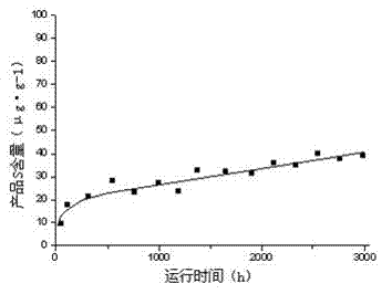
[0030] Coal tar was processed on a continuous hydrogenation test device equipped with 0.5L industrial heavy oil hydrogenation catalyst. The catalyst used is the RHT series hydrogenation catalyst developed by the Beijing Institute of Petroleum Science. The coal tar raw material used in the test comes from the medium-temperature coal tar in northern Shaanxi. Its properties are shown in Table 1. The catalyst type, physical and chemical properties and the loading amount of each catalyst are shown in Table 1. 2. This device adopts the pre-vulcanization technology in the wet in-situ device. The specific vulcanization operating conditions and vulcanization temperature rise are shown in Table 3 and Table 4. The device is at an airspeed of 0.5h -1 , the reaction pressure is 14MPa, the hydrogen oil ratio is 1200:1, the protective agent bed temperature is 300°C, the metal removal agent bed temperature is 350°C, the desulfurization agent bed temperature is 360°C, and the denitrification ...
Embodiment 2
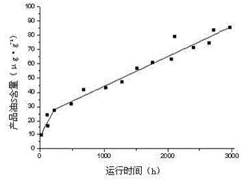
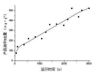
[0037] Raw materials, catalyst and process conditions are consistent with embodiment 1, but continuously inject sulfidation agent CS to the catalyst bed of the device during operation 2 , control the hydrogen sulfide concentration in the circulating hydrogen to 0.07%. The change curve of sulfur and nitrogen content in the product oil with time is shown in image 3 , 4 .
[0038] Depend on image 3 , 4 It can be seen that, and compared with the situation of Example 1 (no sulfur supplementation), sulfur supplementation is continuously added to the reactor during the hydrogenation process, and the hydrogenation product will maintain a high desulfurization rate and denitrification rate within 3000h. Moreover, with the prolongation of time, the sulfur and nitrogen content in the product oil fluctuated less, indicating that sulfur supplementation played a great role in maintaining the activity of the catalyst.
Embodiment 3
[0040] Coal tar was treated on a continuous hydrogenation test device equipped with a 0.5L industrial heavy oil hydrogenation catalyst. The catalyst used was from the FZC series hydrogenation catalyst developed by Fushun Research Institute of Catalysts. The raw material of coal tar for the test came from medium-temperature coal tar in northern Shaanxi. See Table 1 for its properties, and Table 5 for the model and physical and chemical properties of the catalyst and the loading amount of each catalyst. The device is at an airspeed of 0.5h -1 , reaction pressure 14.5MPa, hydrogen-oil ratio 1000:1, protective agent bed temperature 290°C, demetallization agent bed temperature 350°C, desulfurization agent bed temperature 360°C, denitrification agent bed temperature 370°C under the conditions of continuous After running for 3000 hours, the change curve of sulfur and nitrogen content in product oil with time is shown in Figure 5 , 6 .
[0041]
[0042] from Figure 5 , 6 It ...
PUM
 Abstract
Description
Claims
Application Information