Catalytic cracking method for producing propylene

A catalytic cracking and propylene technology, applied in catalytic cracking, cracking, hydrocarbon cracking and hydrocarbon production, etc., to achieve the effects of high high-value product yield, high heavy oil conversion depth, high propylene yield and butene yield

Active Publication Date: 2013-01-30
CHINA PETROLEUM & CHEM CORP +1
View PDF14 Cites 33 Cited by
  • Summary
  • Abstract
  • Description
  • Claims
  • Application Information

AI Technical Summary

Problems solved by technology

[0008] The technical problem to be solved in the present invention is to provide a catalytic cracking method for producing propylene that can increase the yield of propylene and has low dry gas selectivity in view of the shortcomings of the existing catalytic cracking method for producing propylene

Method used


Image

  • Catalytic cracking method for producing propylene
  • Catalytic cracking method for producing propylene
  • Catalytic cracking method for producing propylene

Examples


Embodiment 1

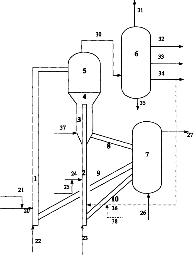
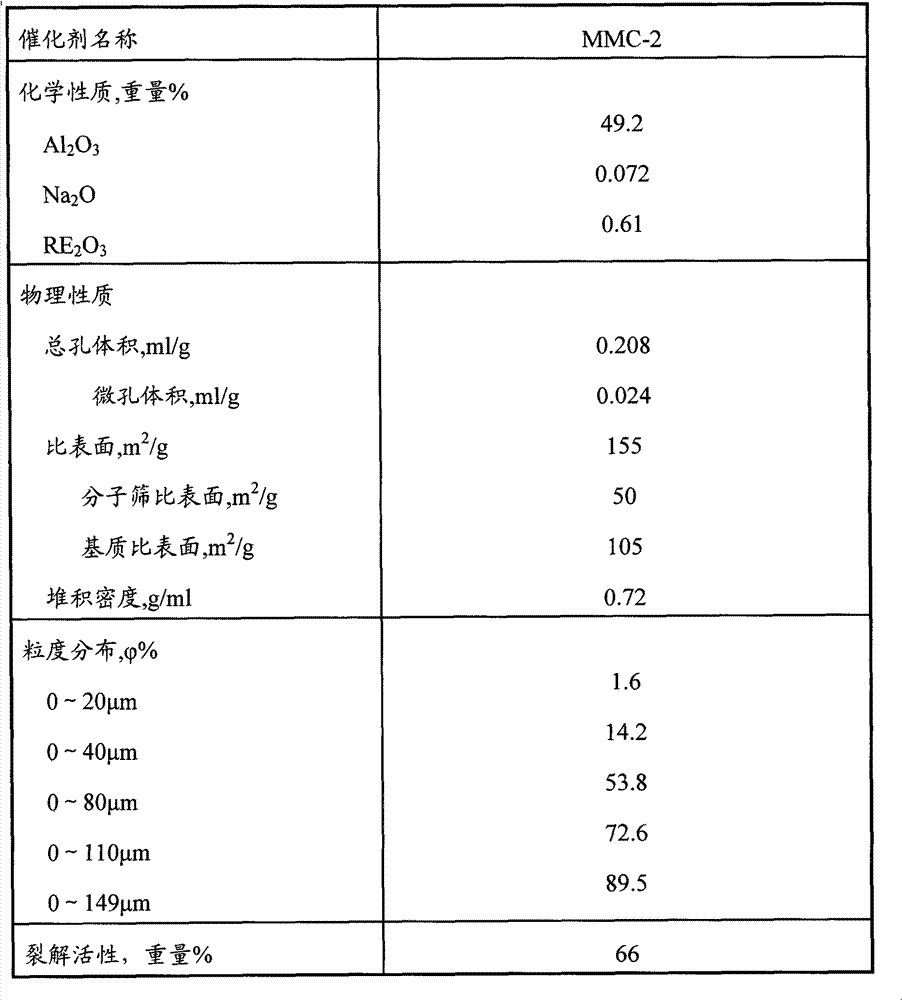
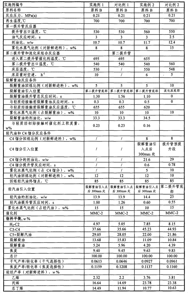
[0043] The experiment was carried out in a medium-sized riser catalytic cracking unit. The inner diameter of the first riser reactor of this medium-sized device is 16 mm, and the length is 3800 mm. The inner diameter of the second riser reactor is 16 mm, and the length is 3200 mm. The outlet of the second riser reactor is connected to the fluidized bed reactor. The inner diameter of the fluidized bed reactor is 64 mm and the height is 600 mm, and its configuration is as follows figure 1 As shown, the test was operated in the way of back refining. A stream of high-temperature regenerated catalyst is introduced into the riser reactor 1 through the regenerated inclined pipe 9, and flows upward under the action of the pre-lift medium (steam); the feed oil B is preheated and mixed with atomized water vapor, and then passes through the feed nozzle Enter the riser reactor 1, contact with the hot regenerant to carry out the catalytic conversion reaction, the reacted oil gas and catal...

Embodiment 2

[0047] Experiments were carried out with reference to the method of Example 1, and the refractory C4 fraction from the product separation system 6 was added to enter the second riser to participate in the reaction, and the reaction operating parameters were adjusted. The reaction conditions and reaction results are shown in Table 3

Embodiment 3

[0049] This example is performed on a medium-sized device, such as figure 1 As shown, in this medium-sized device for continuous reaction-regeneration operation, the internal diameter of riser 1 is 16 mm, and the length is 3800 mm; the internal diameter of riser 2 is 16 mm, and the length is 3200 mm; Bed 3, fluidized bed 3 has an inner diameter of 64 mm and a height of 600 mm. The raw material is atmospheric heavy oil B, and the catalyst is MMC-2. The first stream of high-temperature regenerated catalyst is introduced into the bottom of riser reactor 1 from regenerator 7 through regenerated catalyst delivery pipe 9, and flows upward under the action of steam pre-lifting medium, and then is introduced into riser reactor 1 through pipeline 20. B contact reaction, then enter the settler 5 for oil agent separation, the separated oil and gas are introduced into the product separation system 6, and the catalyst enters the fluidized bed reactor 4; the second regenerated catalytic cr...


PUM

PropertyMeasurementUnit
pore sizeaaaaaaaaaa
lengthaaaaaaaaaa

Abstract

The invention discloses a catalytic cracking method for producing propylene, comprising the following steps: contacting heavy feed stock with a first stream of a catalyst containing shape-selective zeolite with an average pore size being less than 0.7nm in a first riser reactor to conduct cracking reaction, then separating the oiling agent, introducing oil gas into a product separation system, and introducing the catalyst into a stripper or a fluidized bed reactor; contacting the recycled cracking heavy oil with a second stream of the catalyst containing shape-selective zeolite with an average pore size being less than 0.7nm in a second riser reactor to conduct cracking reaction, then letting the obtained oiling agent mixture and the light hydrocarbon introduced into the second riser reactor be subject to contact reaction, then introducing the reaction mixture into a fluidized bed combined reactor for reacting, introducing the reacted oil gas into the product separation system, and introducing the reacted catalyst into the stripper. According to the invention, the method is used for heavy oil catalytic cracking, the heavy oil conversion rate is high, the yields of propylene and butene are high, and the selectivity of dry gas and coke is good.

Description

technical field [0001] The present invention relates to a catalytic cracking method, and more particularly to a method for producing propylene by catalytic cracking of heavy raw materials. Background technique [0002] Catalytic cracking of heavy oil is an important method for the preparation of small molecule olefins such as ethylene, propylene and butene. Industrially used heavy oil catalytic cracking methods to produce light olefins include catalytic cracking technology for maximum production of propylene and catalytic thermal cracking technology for maximum production of ethylene. These two methods use a single riser reactor or a combination of single riser reactors The reactor structure of the fluidized bed cooperates with a special catalyst to react at a higher temperature. The above two methods can produce more low-carbon olefins such as propylene and ethylene, but the dry gas and coke yields are relatively high, and the propylene yield is difficult to further increa...

Claims


Application Information

Patent Timeline
Patent Type & Authority Applications(China)
IPC IPC(8): C10G55/06C07C11/06C07C4/06
CPCY02P20/52Y02P20/584C07C4/06C07C11/06C10G11/16C10G11/18
Inventor 高永灿谢朝钢鲁维民朱金泉崔琰张久顺杨轶男沙有鑫马建国
Owner CHINA PETROLEUM & CHEM CORP
Why Eureka
Try Eureka