Dual-channel rotary optical fiber connector

A rotary connector and dual-channel technology, applied in light guides, optics, instruments, etc., can solve the problems of reduced coupling efficiency, increased transmission loss, and large transmission loss, and achieve high coupling accuracy, low insertion loss, and stable and reliable performance. Effect

Active Publication Date: 2013-02-06
TIANJIN UNIV
View PDF14 Cites 11 Cited by
  • Summary
  • Abstract
  • Description
  • Claims
  • Application Information

AI Technical Summary

Problems solved by technology

However, because the outer channel needs to be coupled multiple times, and the middle part of the channel is coupled with 19 small-diameter plastic optical fibers, the coupling efficiency is low, and the transmission loss is large in practical applications.
Multiple plastic optical fibers in the outer channel also need to be installed precisely, which increases the cost
The third type, as reported in the patent document "US PATENT 7724996 B2 May.25, 2010Gregor Popp, et al.", realizes dual-channel signal transmission that can only be transmitted in a given transmission direction, and because it receives Both ends are oblique incident coupling, the coupling efficiency is low, and the transmission loss is large
[0004] Domestic patents on dual-channel optical fiber rotary connectors include the following categories. One type of patent, as reported by "The People's Republic of China PATENT 00207539.3 Tianjin University", uses a symmetrical optical structure to achieve optical signal transmission, but it can only It is transmitted in a specific direction, and its optical structure coupling accuracy and mechanical structure processing and assembly accuracy are strictly required; the second type of patent is reported in "The People's Republic of China PATENT 200920101680.0 Pulin (Langfang) Optoelectronics Technology Co., Ltd." The channel at the center of the shaft uses a long optical fiber to probe into the central gradient hole of the short optical fiber for coupling. When one end of the optical fiber is rotated, the long optical fiber part will jump, thereby reducing the coupling efficiency; at the same time, the side-axis channel uses the When the reflective surface realizes signal transmission, it will be affected by the axial channel fiber, which will increase the transmission loss

Method used


Image

  • Dual-channel rotary optical fiber connector
  • Dual-channel rotary optical fiber connector

Examples


Embodiment Construction

[0019] The present invention will be described in further detail below in conjunction with specific embodiments.

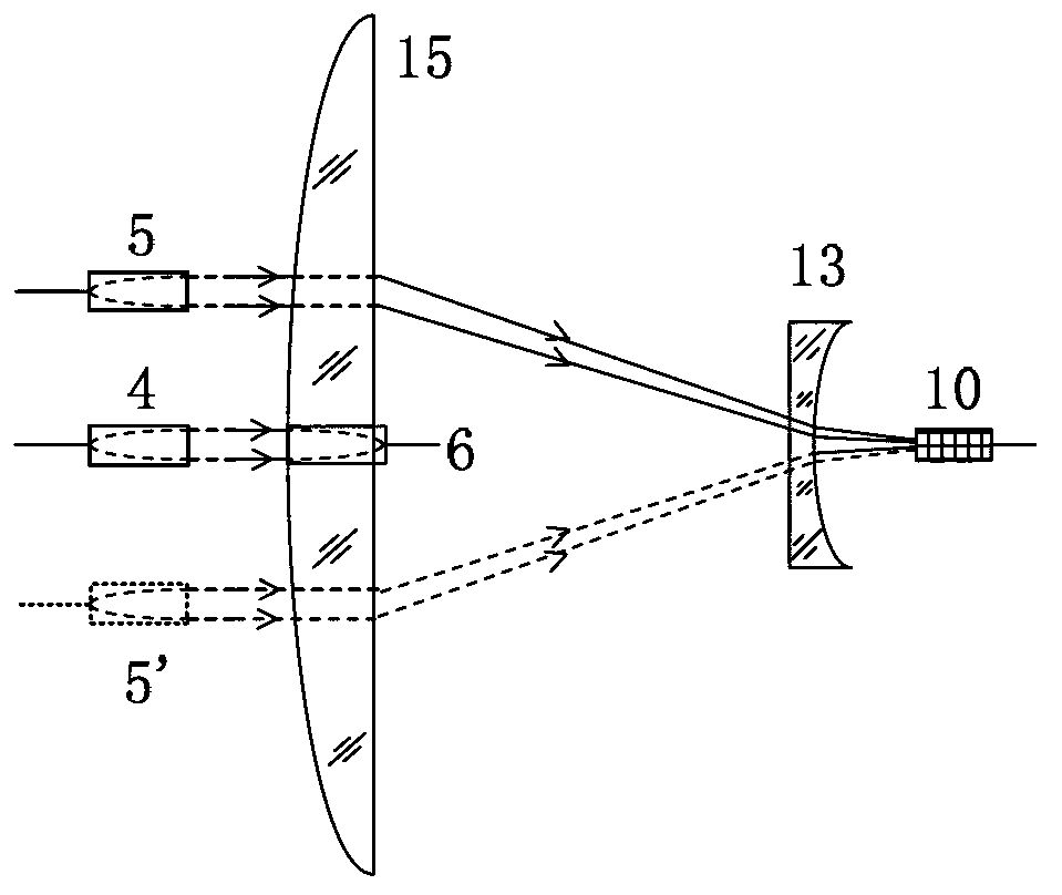
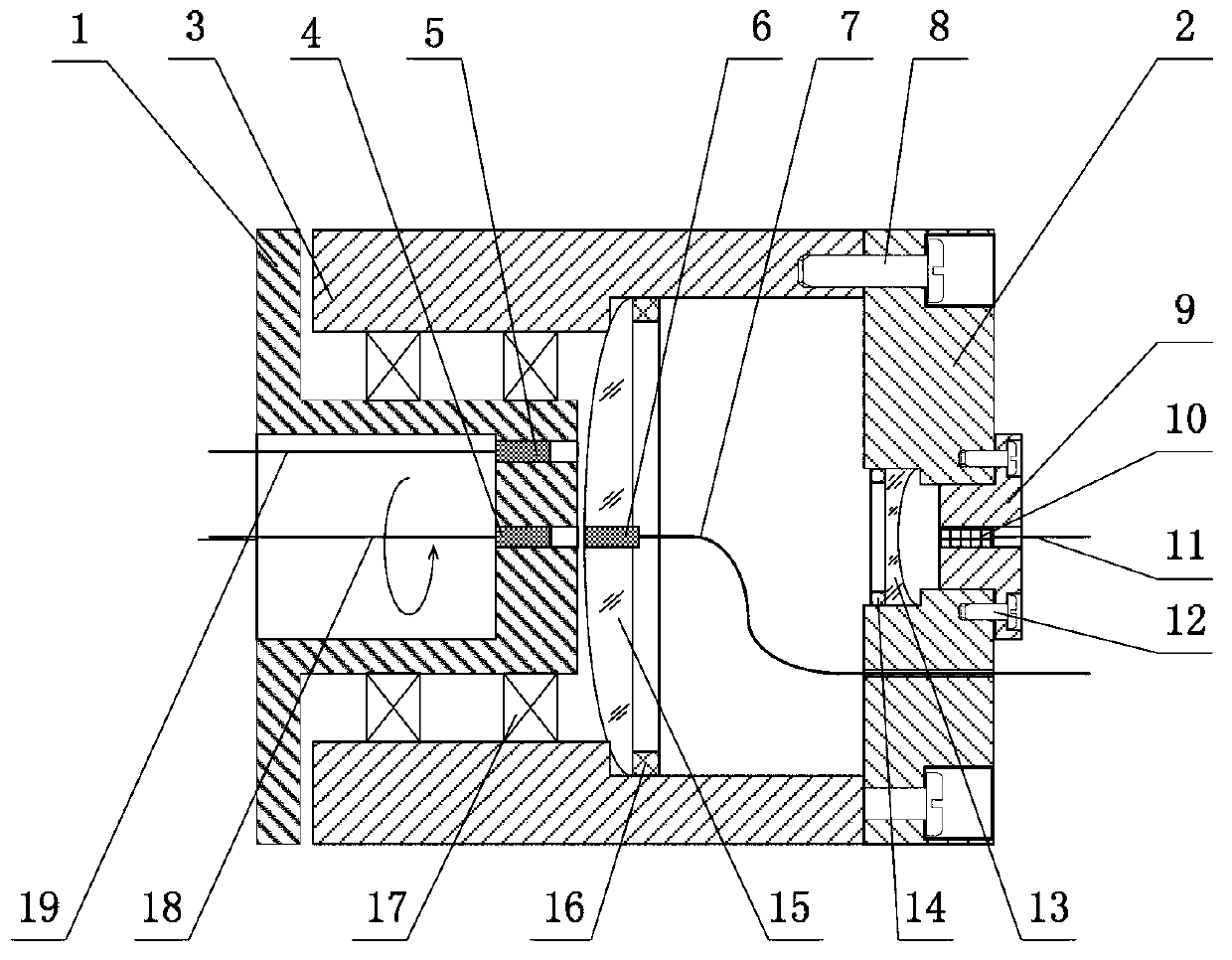
[0020] Such as figure 1 As shown, the basic structure of a dual-channel optical fiber rotary connector of the present invention includes a rotating shaft, a central channel, and a paraxial channel. The central channel is composed of a central incident collimator 4 and a central receiving collimator 6; the paraxial channel is composed of a paraxial incident collimator 5, a convex lens 15, a concave lens 13 and a paraxial receiver 10. The central incident collimator 4, the central receiving collimator 6 and the paraxial receiver 10 are all arranged on the rotation axis; the paraxial incident collimator 5 is eccentrically arranged with respect to the rotation axis, and The rotation axis is parallel; a center hole is punched in the center of the convex lens 15 to fix the center receiving collimator 6; the optical axes of the convex lens 15 and the concave lens 13 are coa...


PUM


Abstract

The invention discloses a dual-channel rotary optical fiber connector. The connector comprises a central channel and a paraxial channel; a central incident collimator and a central receiving collimator, which are positioned on a rotating shaft, form the central channel of the rotary connector through direct aligned coupling and realize rotary and continuous transmission of optical signals in the central channel; a convex lens and a concave lens which are coaxial with the rotary connector, a paraxial incident collimator, and a paraxial receiver on an axis form the paraxial channel of the rotary connector; the paraxial incident collimator emits parallel light which passes through the convex lens and the concave lens and then enters the paraxial receiver, and rotary and continuous transmission of paraxial optical signals is guaranteed through the axial symmetry of the lens; the distance between the convex lens and the concave lens is determined by the paraxial receiver; the paraxial receiver can be an optical fiber collimator or large-core-diameter optical fibers; and a small hole is formed in the center of the convex lens and is used for fixing the central receiving collimator. The dual-channel rotary optical fiber connector has the advantages of simple structure, low insertion loss, high coupling precision and stable and reliable performance.

Description

Technical field [0001] The invention belongs to the technical field of optical fiber communication, and particularly relates to a dual-channel optical fiber rotary connector, and is particularly applied to the rotary coupling transmission of optical signals having two channels between relative rotating devices. Background technique [0002] Optical fiber rotary connector is a mechanism that uses optical fiber as a transmission medium to transmit signals between a rotating platform and another stationary platform. At present, this type of device is widely used in different fields, such as the antenna system of the scanning and tracking radar in the military field, the gun mount or the turret of the tank, etc.; in the industry, such as submarine sonar information acquisition system, oil well drilling equipment, robots System, industrial process control, etc.; CT scanning system for medical equipment and information transmission system for spacecraft. The device needs to strictly g...

Claims


Application Information

Patent Timeline
Patent Type & Authority Applications(China)
IPC IPC(8): G02B6/32G02B6/38
CPCG02B6/3604
Inventor 贾大功许强张红霞刘铁根张以谟
Owner TIANJIN UNIV
Why Eureka
Try Eureka