
Hydrogen sulfide tail gas treatment system and method

A technology for tail gas treatment and hydrogen sulfide, which is applied in chemical instruments and methods, separation methods, sulfur preparation/purification, etc., can solve the problems of polluted atmosphere, unstable treatment effect, low utilization value of alkali sulfide, etc., and achieves great economic significance. , The effect of processing the effect is stable

Inactive Publication Date: 2013-02-13
CHINA PETROLEUM & CHEM CORP +1
View PDF3 Cites 11 Cited by
  • Summary
  • Abstract
  • Description
  • Claims
  • Application Information

AI Technical Summary

Problems solved by technology

Claus furnace treatment uses sulfur recovery catalyst at high temperature to obtain elemental sulfur, and hydrogen atoms are converted into water, which cannot comprehensively utilize valuable hydrogen resources and is suitable for larger industrial scales; alkali absorption treatment uses alkaline substances (hydrogen oxidation Sodium solution, ammonia water, etc.) to neutralize hydrogen sulfide (such as patent number: 200720123284.9, named: hydrogen sulfide tail gas treatment device), produce alkali sulfide with low utilization value, and with the consumption of alkaline substances, the treatment effect is unstable
The above two types of methods limit the promotion and application of hydrogen sulfide treatment and recovery facilities, and some enterprises can only use the method of tail gas incineration treatment, resulting in excessive sulfur dioxide emissions and air pollution

Method used


Image

  • Hydrogen sulfide tail gas treatment system and method

Examples


Embodiment 1

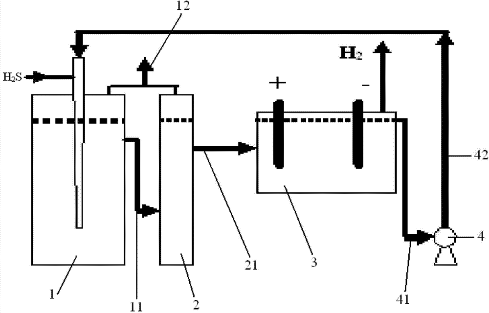
[0017] A hydrogen sulfide tail gas treatment system, comprising an absorption tank 1, a settling tank 2, an electrolytic tank 3 and a sequential pump 4; the hydrogen sulfide tail gas is transported to the absorption tank 1, and Fe 3+ Aqueous solution; the upper part of the side wall of the absorption tank 1 is provided with a first overflow pipe 11, and the overflow pipe 11 is communicated with the settling tank 2, and the tops of the absorption tank 1 and the settling tank 2 are all provided with a tail gas discharge pipe 12; The upper part of the side wall of the settling tank 2 is provided with a second overflow pipe 21, and the overflow pipe 21 communicates with the electrolytic tank 3; the inlet end of the circulation pump 4 communicates with the electrolytic tank 3 through the first pipeline 41, and the circulation The outlet end of the pump 4 is connected to the absorption pool 1 through the second pipe 42 .

[0018] The method for utilizing the above-mentioned system t...


PUM


Abstract

The invention relates to a hydrogen sulfide tail gas treatment system and a hydrogen sulfide tail gas treatment method. The hydrogen sulfide tail gas treatment system comprises an absorption tank, a settling tank, an electrolytic tank and a circulating pump, wherein an oxidant solution is filled into the absorption tank; a first overflow pipe is arranged on the upper part of the side wall of the absorption tank and is communicated with the settling tank; tail gas discharge pipes are arranged on the top of the absorption tank and the top of the settling tank respectively; a second overflow pipe is arranged on the upper part of the side wall of the settling tank and is communicated with the electrolytic tank; the inlet end of the circulating pump is communicated with the electrolytic tank by a first pipeline; and the outlet end of the circulating pump is communicated with the absorption tank by a second pipeline. According to the hydrogen sulfide tail gas treatment system, hydrogen sulfide is converted into a sulphur simple substance and hydrogen by oxidation reduction reaction, so that the hydrogen sulfide is utilized fully, reaction liquid is recycled, a treatment effect is stable, precious hydrogen resources can also be produced, and the hydrogen sulfide tail gas treatment system has the great economic significance on a large-scale treatment device; and the hydrogen sulfide in tail gas can be absorbed economically, efficiently, conveniently and stably.

Description

technical field [0001] The invention relates to the field of chemical tail gas treatment, in particular to a hydrogen sulfide tail gas treatment system and method. Background technique [0002] Existing hydrogen sulfide tail gas treatment equipment mainly adopts Claus furnace treatment (industrial scale) or alkali absorption treatment. Claus furnace treatment uses sulfur recovery catalyst at high temperature to obtain elemental sulfur, and hydrogen atoms are converted into water, which cannot comprehensively utilize valuable hydrogen resources and is suitable for larger industrial scales; alkali absorption treatment uses alkaline substances (hydrogen oxidation Sodium solution, ammonia water, etc.) to neutralize hydrogen sulfide (such as patent number: 200720123284.9, named: hydrogen sulfide tail gas treatment device), to produce alkali sulfide with low utilization value, and with the consumption of alkaline substances, the treatment effect is unstable. The above two types o...

Claims


Application Information

Patent Timeline
Patent Type & Authority Applications(China)
IPC IPC(8): B01D53/78B01D53/52C01B17/05C25B1/02
Inventor 石宁谢传欣徐伟孟庭宇张海峰
Owner CHINA PETROLEUM & CHEM CORP
Learn More