Anti-coking device for high-temperature pyrolysis gas inlet of oil gas quench cooler

A high-temperature cracking and anti-coking technology, which is applied in cracking, petroleum industry, catalytic cracking, etc., can solve the problems of hindering the passage of cracked gas, increasing the pressure drop at the outlet of oil and gas, and serious coking, so as to reduce production and maintenance costs and prolong Production cycle, the effect of improving production efficiency

Active Publication Date: 2014-08-13
SHENYANG PARAFFIN CHEM
View PDF6 Cites 2 Cited by
  • Summary
  • Abstract
  • Description
  • Claims
  • Application Information

AI Technical Summary

Problems solved by technology

However, the existing quenching boilers often have the following disadvantages: the temperature of the cracked gas at the high-temperature oil and gas inlet of the oil-gas quencher is high and changes rapidly, so the coking is serious, which quickly blocks the oil and gas outlet, hinders the passage of the cracked gas, and causes a rapid pressure drop at the oil and gas outlet. The temperature rises, and the high-temperature oil and gas are unevenly distributed, resulting in uneven cooling of the entire quench cooler. After the cracked gas is fully cooled, the high-boiling point components condense on the heat transfer tube wall, and the dehydrogenation polycondensation reaction slowly proceeds, gradually becoming heavy, successively Turn into tar-like or coke-like substances, causing the entire equipment to quickly coke and block
Therefore, regular shutdowns are required for emergency repairs, and the entire device cannot operate stably for a long time, which increases production and maintenance costs

Method used


Image

  • Anti-coking device for high-temperature pyrolysis gas inlet of oil gas quench cooler
  • Anti-coking device for high-temperature pyrolysis gas inlet of oil gas quench cooler

Examples


Embodiment 1

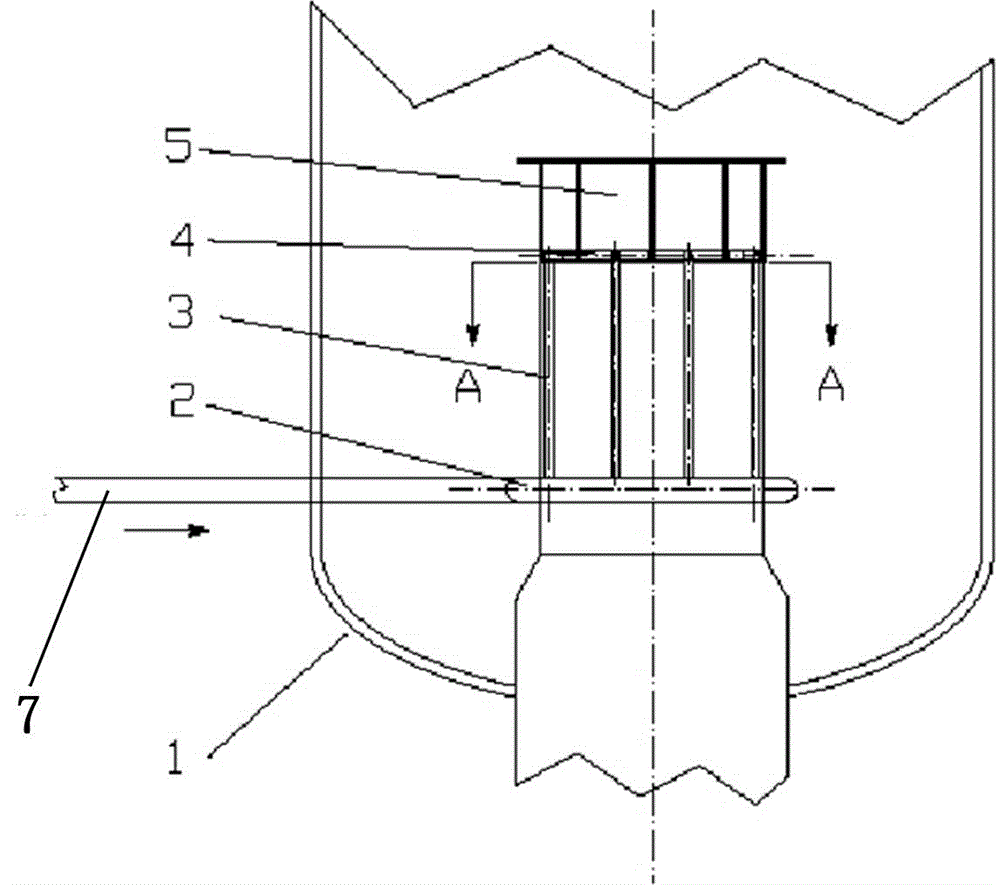
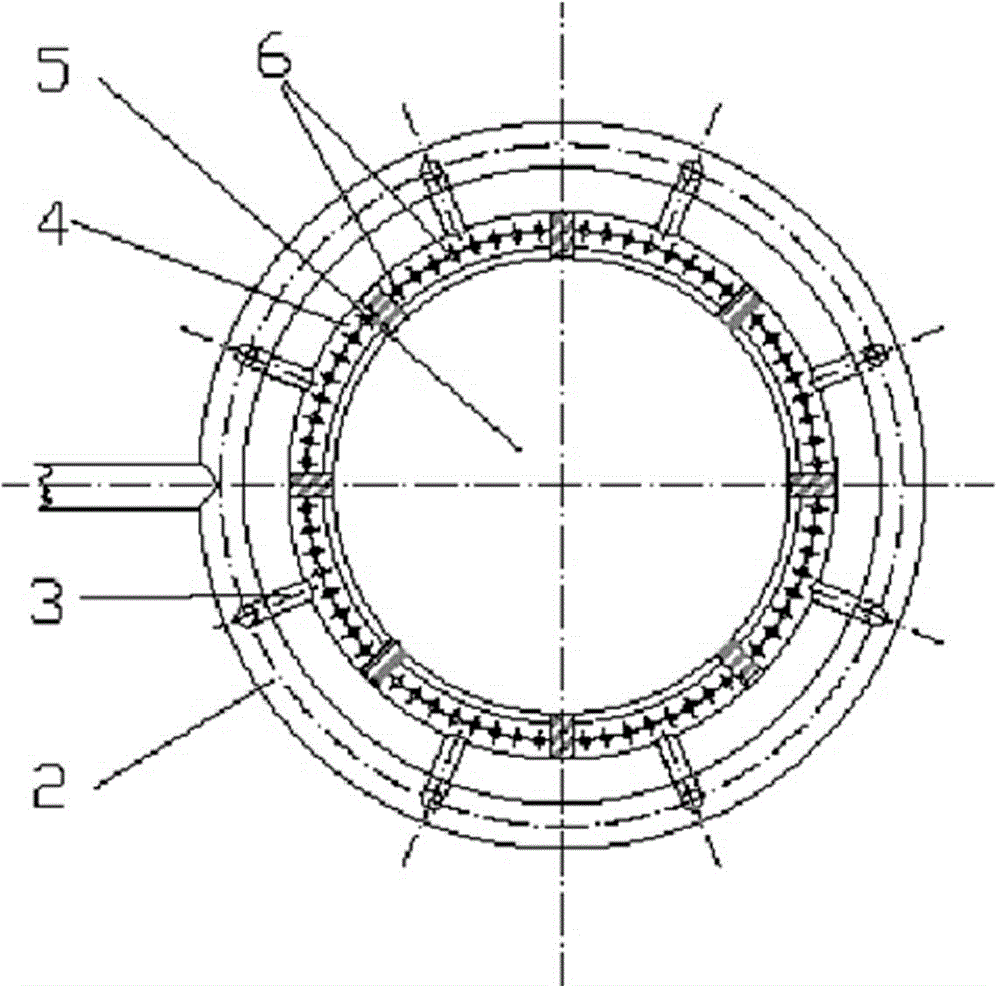
[0022] Such as figure 1 and figure 2 The shown quenching boiler 1 of the present invention is equipped with an anti-coking device at the high-temperature cracked gas inlet of an oil-gas quenching device at the bottom. Ring pipe 4, eight steam holes 6 are arranged on each section of the anti-coking steam ring pipe, and eight vertical distribution pipes 3 are arranged in sequence from the oil and gas outlet 5 from top to bottom. The pipe 2 and the distribution pipe 3 are evenly distributed on the outer wall of the air inlet pipe. The anti-coke steam ring pipe 4 communicates with the distribution ring pipe 2 through the vertical distribution pipe 3. The distribution ring pipe 2 is provided with a steam inlet 7.

[0023] The steam enters the distribution ring pipe 2 of the anti-coking device at the bottom of the quenching boiler 1 from the anti-coking steam inlet 7, and then enters the eight-stage anti-coking steam ring pipe 4 along the 8 vertical distribution pipes, and then pa...

Embodiment 2

[0026] Steam holes can also be provided on the distribution pipe 3 and / or the distribution ring pipe 2 to prevent other parts of the pipe from coking.


PUM


Abstract

The anti-coking device at the high-temperature pyrolysis gas inlet of the oil-gas quencher, the anti-coking device is a hollow air intake pipe, and its technical key points are: an anti-coking steam ring pipe is arranged concentrically at the oil and gas outlet of the air intake pipe, and steam holes are arranged on the anti-coking steam ring pipe , from the oil and gas outlet, the distribution pipe and the distribution ring pipe are arranged sequentially from top to bottom, the anti-coking steam ring pipe and the distribution ring pipe are connected through the distribution pipe, and the distribution ring pipe is provided with a steam inlet. The advantages of the present invention: After the existing quenching equipment is transformed, the problem of easy coking at the inlet of the quenching equipment is solved, and the effect is remarkable; the partial pressure of hydrocarbons is reduced, and the yield is improved; no regular shutdown and maintenance is required, the production cycle is prolonged, and the production rate is improved. Improve production efficiency, reduce production and maintenance costs.

Description

technical field [0001] The invention relates to the technical field of chemical equipment, further relates to a device for preventing coking at the high-temperature oil and gas inlet of an oil-gas quencher, and further relates to a coking-preventing quenching heat exchange device. Background technique [0002] Cracking refers to the process in which petroleum-based hydrocarbon raw materials undergo carbon chain scission or dehydrogenation reaction at high temperature to generate olefins and other products. Among them, ethylene and propylene are mainly produced, and by-products such as olefins such as butene and butadiene, and pyrolysis gasoline, diesel oil, fuel oil and other products are also produced. To realize the cracking reaction in industry, the following requirements must be met: supply a large amount of heat to the reactants and keep the system under high temperature conditions; due to the short residence time, the reaction materials must be given a large amount of ...

Claims


Application Information

Patent Timeline
Patent Type & Authority Patents(China)
IPC IPC(8): C10G11/00
Inventor 李惠武王明伟孙章贾立军
Owner SHENYANG PARAFFIN CHEM
Why Eureka
Try Eureka