Ultra-large high-efficiency high-operation-flexibility high-throughput anti-blocking composite flow-through tray

A through-flow tower and through-flow technology, which is applied in the field of large-scale composite through-flow trays, can solve the problems of short vapor-liquid contact time, high space utilization rate, and low mass transfer efficiency, so as to increase the gas-liquid contact area and time, Improve efficiency and reduce tray pressure drop effect

Active Publication Date: 2014-01-15
CHINA UNIV OF PETROLEUM (EAST CHINA)
View PDF6 Cites 0 Cited by
  • Summary
  • Abstract
  • Description
  • Claims
  • Application Information

AI Technical Summary

Problems solved by technology

Trays can be divided into overflow trays and through-flow trays according to whether there is a downcomer. In contrast, the existing through-flow trays have simple structure, high space utilization in the tower, low cost, and high processing capacity. Large, but the vapor-liquid contact time is short, the mass transfer efficiency is low, and the operating flexibility is small; the ultra-large through-flow tray support ring and the strict requirements for installation levelness are too strict, and there is an amplification effect, so it is urgent to solve the ultra-large support structure of the tray Difficulties and plate strength issues

Method used


Image

  • Ultra-large high-efficiency high-operation-flexibility high-throughput anti-blocking composite flow-through tray
  • Ultra-large high-efficiency high-operation-flexibility high-throughput anti-blocking composite flow-through tray

Examples


Embodiment 1

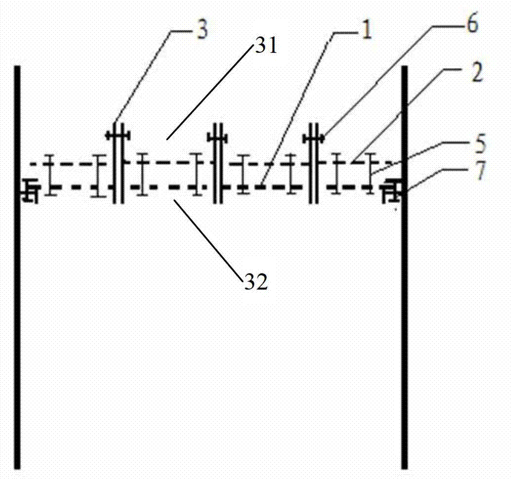
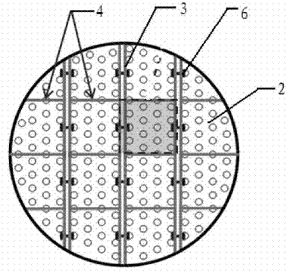
[0014] Example 1, such as figure 1 , figure 2 As shown, the present invention is assembled into a tray by several strip composite through-flow trays. The composite through-flow tray is composed of a through-flow tray 1, a through-flow sieve tray 2, an H-shaped vertical edge 3 and a partition 4. The through-flow tray 1 is a flat plate with a thickness of 2 to 10 mm, and there are holes on it. 20 to 60% of the diameter or equivalent diameter of 15 to 20 mm round hole or rhombus hole; at a distance of 3 to 8 mm in the upper part of the through-flow tray 1, a plurality of fixed columns 5 are used to fix the through-flow with the same opening ratio and hole shape The sieve plate 2, the fixed column 5 and the through-flow tray 1 and the through-flow sieve plate 2 can be welded or bolted. The plate thickness of the through-flow sieve plate 2 is 2-10 mm; the sieve holes or diamond-shaped holes on the through-flow sieve plate 2 and the through-flow tray 1 are staggered or partially ...

Embodiment 2

[0016] Embodiment 2, can refer to figure 1 , figure 2 , the present invention is made up of through-flow tray 1, through-flow sieve plate 2, H-shaped vertical edge 3 and dividing plate 4, and through-flow tray 1 is the flat plate with the thickness of 2~10mm, has opening ratio 20~ 60% of strip-shaped holes with a width of 6-20mm and a length of 30-200mm; a through-flow sieve plate with the same opening ratio and hole shape fixed by multiple fixing columns 5 at a distance of 3-8mm high on the upper part of the through-flow tray 1 2. The fixed column 5 and the through-flow tray 1 and the through-flow sieve plate 2 can be welded or bolted. The plate thickness of the through-flow sieve plate 2 is 2-10 mm; the strip holes on the through-flow sieve plate 2 and the through-flow tray 1 are staggered or partially staggered; the H-shaped vertical edge 3 is vertically fixed on the through-flow tray 1 and the Both ends of the through-flow sieve plate 2, the upper and lower ends of the ...


PUM


Abstract

The invention provides an ultra-large high-efficiency high-operation-flexibility high-throughput anti-blocking composite flow-through tray. According to the invention, a staggered flow-through sieve plate with a porosity same with that of a high-porosity flow-through tray is fixed on the upper part of the high-porosity flow-through tray. Integrally, blocked mounting is carried out according to an H-shaped vertical edge. The H-shaped vertical edge serves as a self supporting beam of the composite flow-through tray. A perpendicular separation plate is arranged on an upper groove. With the H-shaped vertical edge and the separation plate, the entire tray is divided into a plurality of mixing tanks, such that pressure drop can be reduced, gas-liquid contact area and time can be increased, and throughput and operation flexibility can be greatly improved. Gas bubble breaking and thinning, and interface updating enhancing functions are provided among trays, such that the efficiency of the composite flow-through tray is greatly improved. Tray ultra-large supporting rings, strict requirements on mounting levelness, and an amplification effect are eliminated. A tray ultra-large supporting structure difficulty and a tray strength problem are solved. Therefore, tower upsizing can be easily realized.

Description

technical field [0001] The invention relates to the field of separation equipment, in particular to a large composite through-flow tray. Background technique [0002] In petrochemical, petroleum refining, chemical industry, light industry, environmental protection, medicine and atomic energy and other industrial sectors, trays and packing are widely used in chemical unit processes such as distillation, absorption, extraction, absorption, washing and cooling. Packing has the advantages of high separation efficiency, small pressure drop, and large processing capacity, but the cost is high, the operation flexibility is small, and the requirements for supporting column internals are high; the tray has high operation flexibility, anti-clogging, low cost, and relatively high separation efficiency , but the pressure drop will be larger and the processing capacity will be lower. The ideal column internals should have the characteristics of low pressure drop, high efficiency, large ...

Claims


Application Information

Patent Timeline
Patent Type & Authority Patents(China)
IPC IPC(8): B01D3/14
Inventor 田原宇乔英云
Owner CHINA UNIV OF PETROLEUM (EAST CHINA)
Why Eureka
Try Eureka