Method for positioning permanent magnet synchronous motor rotor initial position

A technology of permanent magnet synchronous motor and rotor initial position, which is applied in the control of generators, electronic commutators, motor generator control, etc., can solve the problem of inability to achieve full automation, and achieve high positioning accuracy, stable operation, and simple methods. Effect

Active Publication Date: 2013-02-20
BEIJING INSTITUTE OF TECHNOLOGYGY
View PDF4 Cites 42 Cited by
  • Summary
  • Abstract
  • Description
  • Claims
  • Application Information

AI Technical Summary

Problems solved by technology

This method of manually turning the motor relies on manual assistance and cannot achieve fully automatic motor control

Method used


Image

  • Method for positioning permanent magnet synchronous motor rotor initial position
  • Method for positioning permanent magnet synchronous motor rotor initial position
  • Method for positioning permanent magnet synchronous motor rotor initial position

Examples


Embodiment Construction

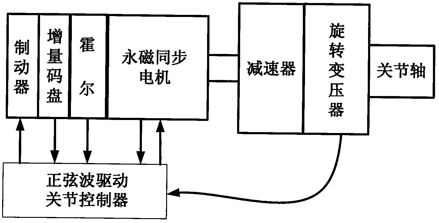
[0019] figure 1 It is a structural block diagram of a permanent magnet synchronous motor servo drive system according to the present invention. The servo drive system is composed of a permanent magnet synchronous motor, a Hall element, an incremental code disc, a brake, a rotary transformer and a sine wave drive controller. Among them, the Hall element is used to detect the position information of the motor during the initial positioning of the motor rotor; the code disc is used to detect the position information and speed information of the motor when the sine wave is driven; the brake is used to lock the motor during positioning; the resolver is used to detect the servo Information about the location of the drive system.

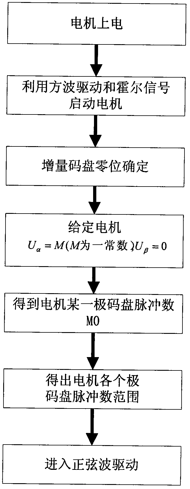
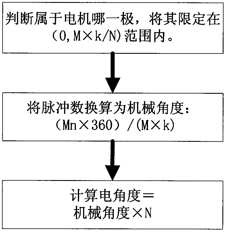
[0020] Assume that the permanent magnet synchronous motor used is N poles, the incremental code disc is M lines, and the frequency multiplication is k. The initial position positioning of the motor rotor includes two steps. First, the motor is started by ...


PUM


Abstract

The invention discloses a method for positioning a permanent magnet synchronous motor rotor initial position. Firstly a motor is started by a square wave drive mode and rotor position information detected by a hall element, then sine wave drive is started, and number of pole-pairs of the motor is positioned. By means of the method for positioning the permanent magnet synchronous motor rotor initial position, the full automation of the motor from starting to operating can be achieved, external force or manual starting is not required, simultaneously the method is simple, and the accuracy is high.

Description

technical field [0001] The invention relates to a new method for positioning the initial position of a rotor of a permanent magnet synchronous motor, which is simple and has high precision. Background technique [0002] Permanent magnet synchronous motors have high power density, high efficiency, fast dynamic response, and precise positioning. These advantages make permanent magnet synchronous motors, as AC servo motors, increasingly widely valued and used in position servo control systems. [0003] In the position servo control system, the rotor position angle of the permanent magnet synchronous motor is very important control information. Without the position angle, it is difficult to determine the control state of the stator winding, and the motor may experience speed oscillation or even out of step, let alone achieve high precision. Position servo control. However, due to the presence of permanent magnets in the rotor, the position of the magnetic poles at zero speed is...

Claims


Application Information

Patent Timeline
Patent Type & Authority Applications(China)
IPC IPC(8): H02P6/16H02P6/20H02P21/18H02P21/34
Inventor 蒋志宏李丹凤黄强李辉
Owner BEIJING INSTITUTE OF TECHNOLOGYGY
Why Eureka
Try Eureka